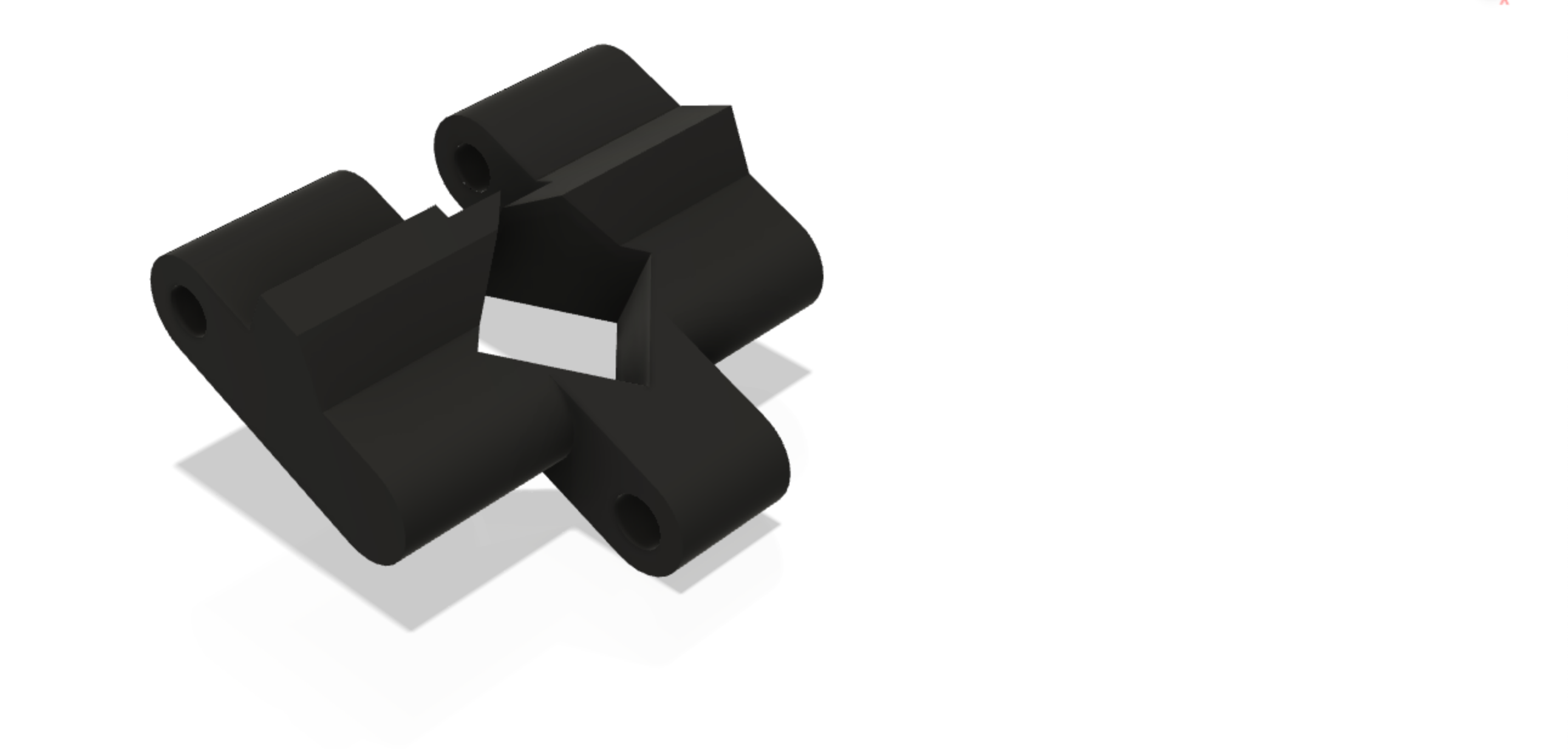
Track Design
SMARS Track Design
Watch the step by step guide of how to create the track using Fusion 360.
Profiles
The Tracks have three main profiles:
A PDF containing these profiles is available here.
Note
It’s likely that printing out 16 of these parts and connecting them together in a chain will amplify any tolerance errors from your 3d printer (or from the design). If you find the printed parts are too tight or too slack, you can stretch the part in your slicing software on the Y-axis by a tiny amount - try 0.05 to 0.1mm at a time (increase to make a tight-fit slacker, or decrease to make a slack-fit tighter). Remember that connecting the pieces together multiplies this tolerance, so an increase of 0.05mm will be 16 x 0.05mm or 0.8mm across the whole length of the track.
Dimensions Table
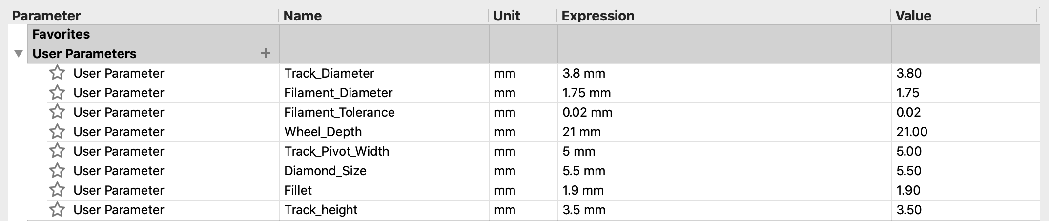
| Dimension | Value |
|---|---|
| Track_Diameter | 3.8mm |
| Wheel_Depth | 21mm |
| Filament_Diameter | 1.75mm |
| Filament_Tolerance | 0.02mm |
| Track_Pivot_Width | 5mm |
| Diamond_Size | 5.5mm |
| Fillet | 1.9mm |
| Track_height | 3.5mm |
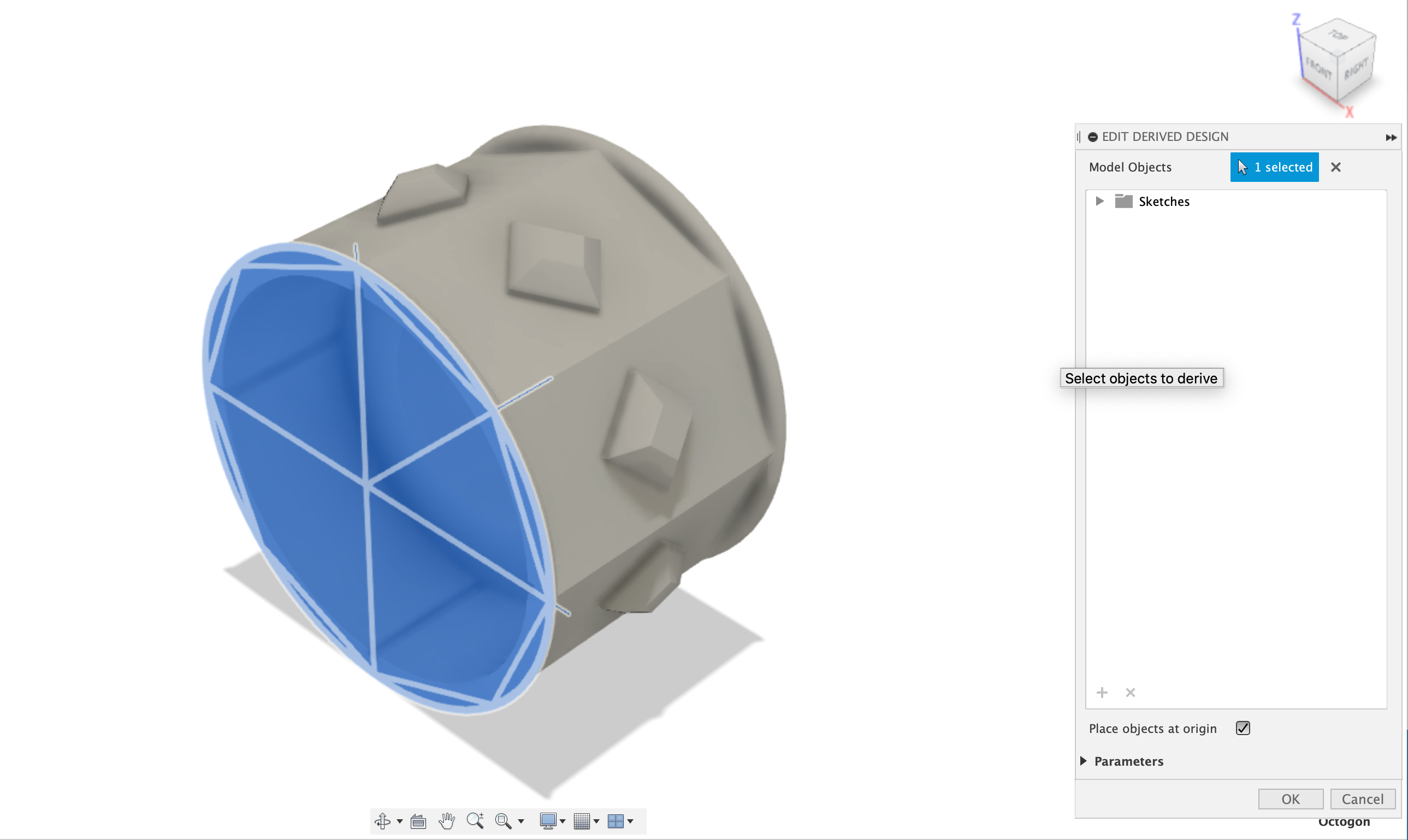
Derive the first sketch from the Unpowered Wheel
The base sketch will be derived from the Unpowered Wheel, as any changes to the unpowered wheel need to be reflected in this design. To derive the design, first save the design, then click Insert and Insert Derived from the menu. Next, select the octagon profile from the list.
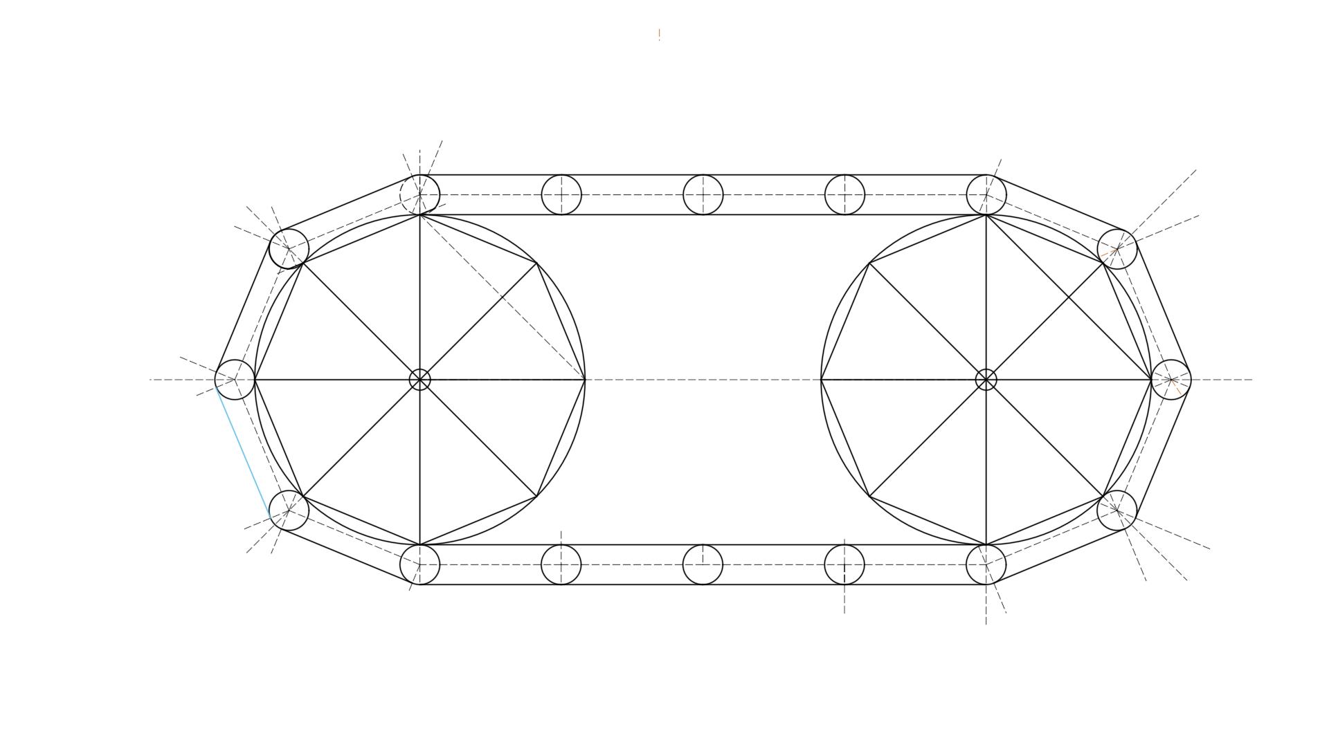
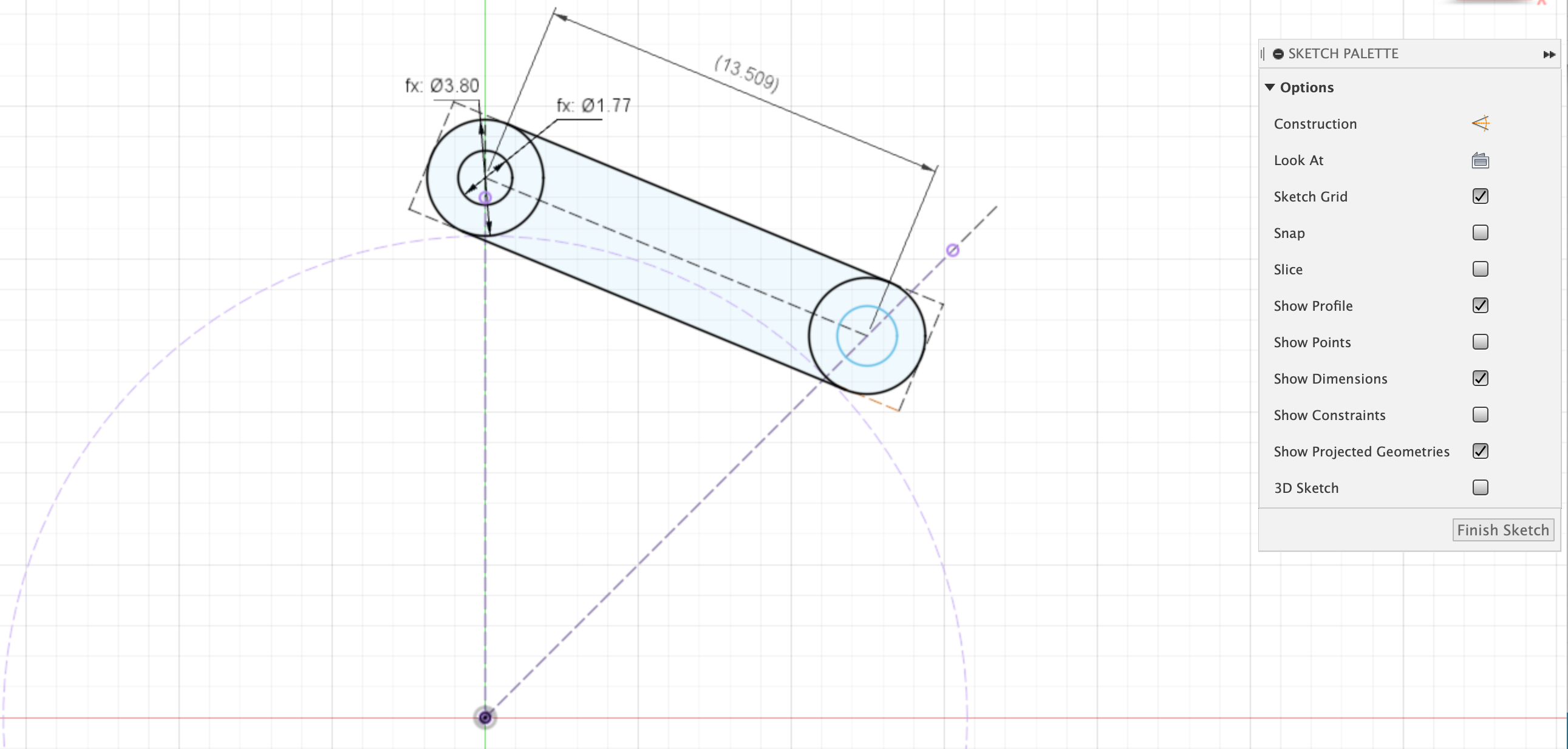
The Base Profile
The base sketch consists of two circles that are tangent to the projected profile of the unpowered wheels inscribed octogon sketch. The length of the track section is implied by these circles. Two lines are added between the top and bottom of these circles to for the main track profile.
Dimensions:
- Length = 13.509mm - note this dimensions is not specified, it is implied by the constraints.
- Pivot_Hole_Diameter = Filament_Diameter + Filament_Tolerance (1.77mm)
- Track_Diameter = 3.8mm
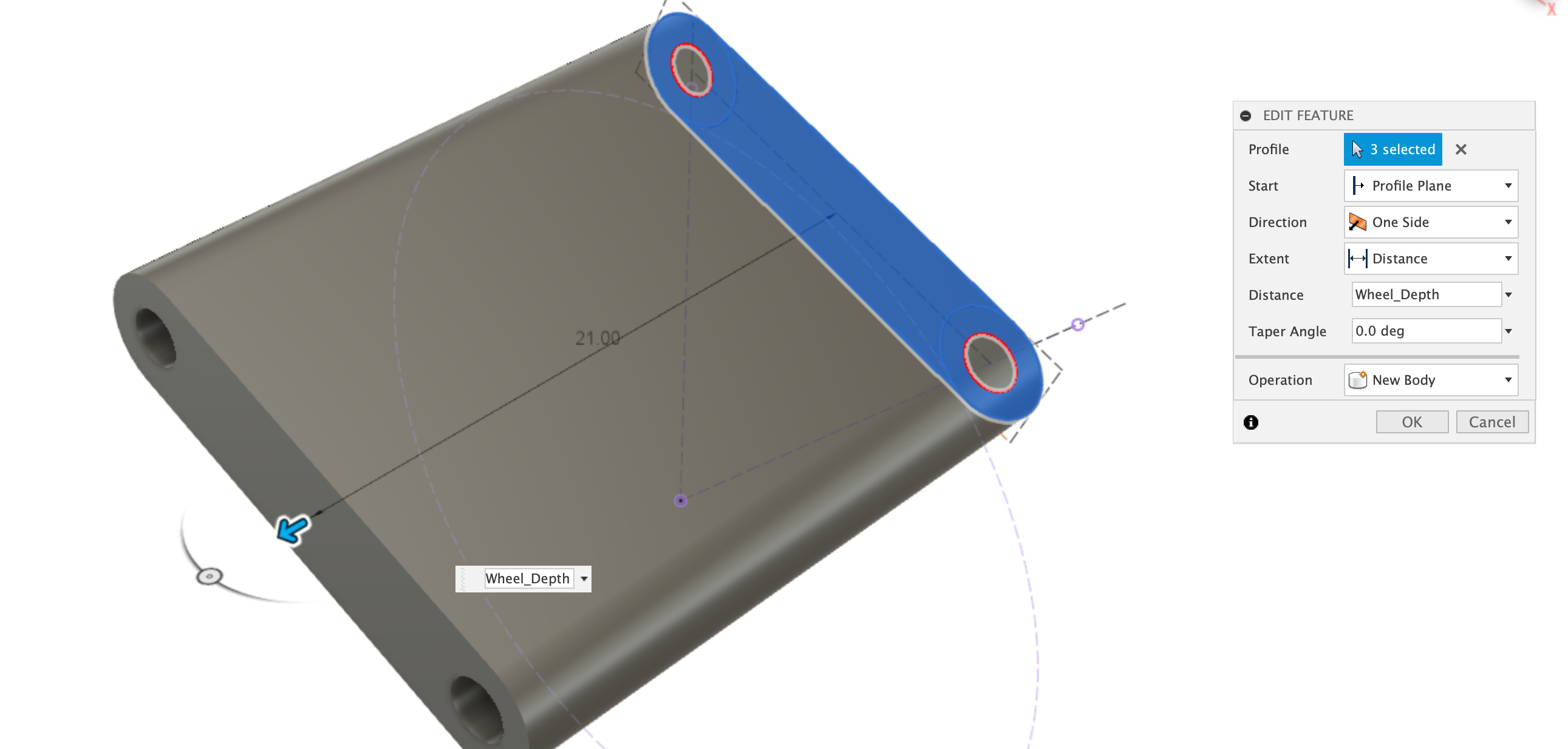
Extrude Base Profile
Next, the base profile is extruded by the wheel_depth distance.
Dimensions:
- Wheel_Depth = 21mm
Top Profile
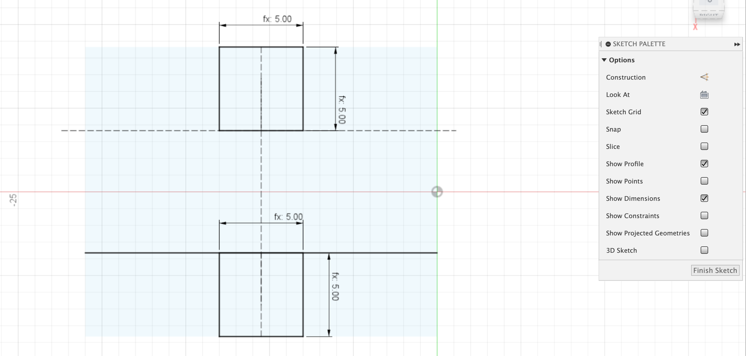
Create a new sketch on the top of the newly extruded body. We will now create the main outline of the Track. Its essentially two squares of the same dimensions (5mm), which we call the Track Pivot at the top and cut out of the bottom. The squares are aligned down the centerline of the body. A line is drawn across the body, which is colinear with the top edge of the bottom square.
Dimensions:
- Track_Pivot_Width = 5mm
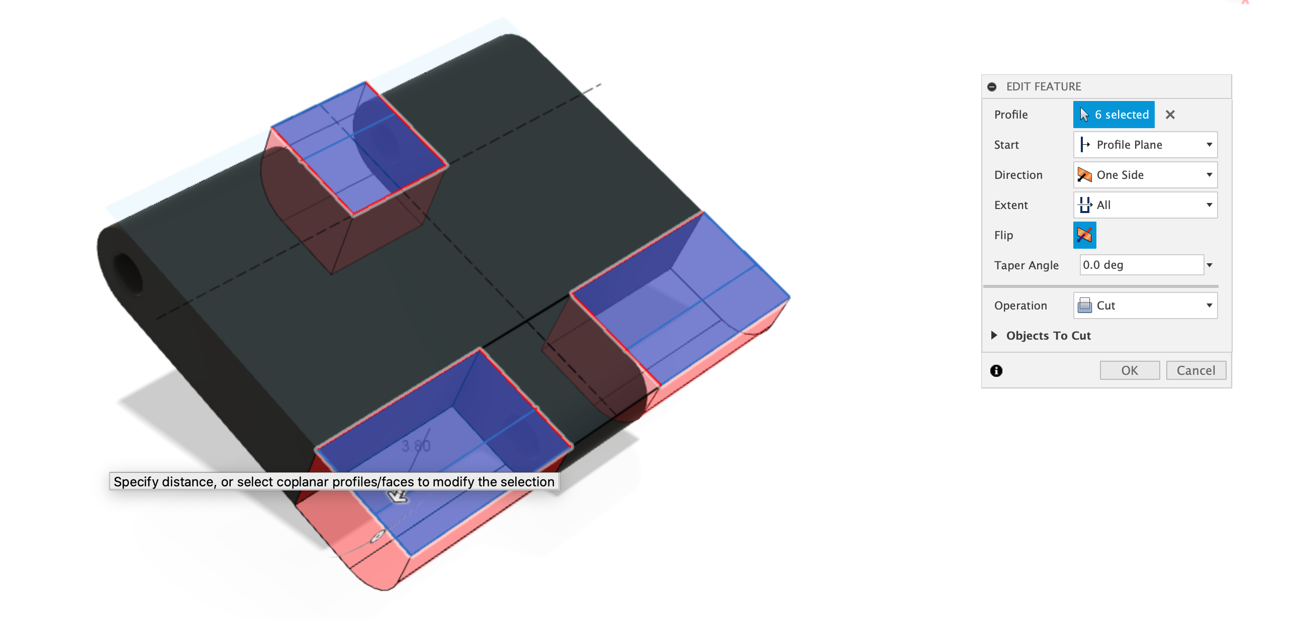
Extrude Cut Profile
The profile is then used to extrude-cut into the body, selecting the parts as illustrated below. The cut goes all the way through the body.
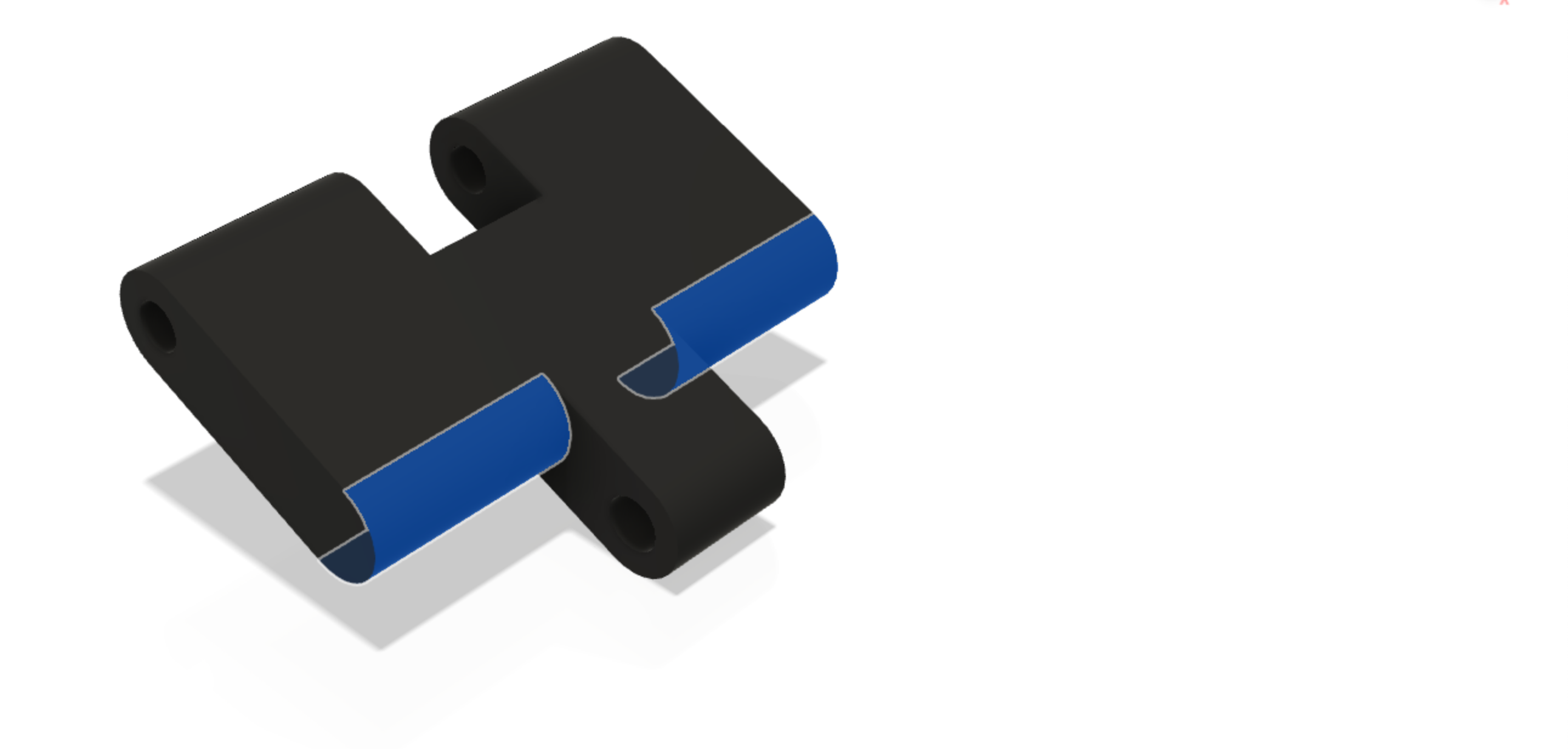
Fillet the edges
The newly formed edges now need to have a fillet applied to them, to make them look the same as the top and bottom rounded edges. The fillet is 1.9mm.
Dimensions:
- Fillet = 1.9mm
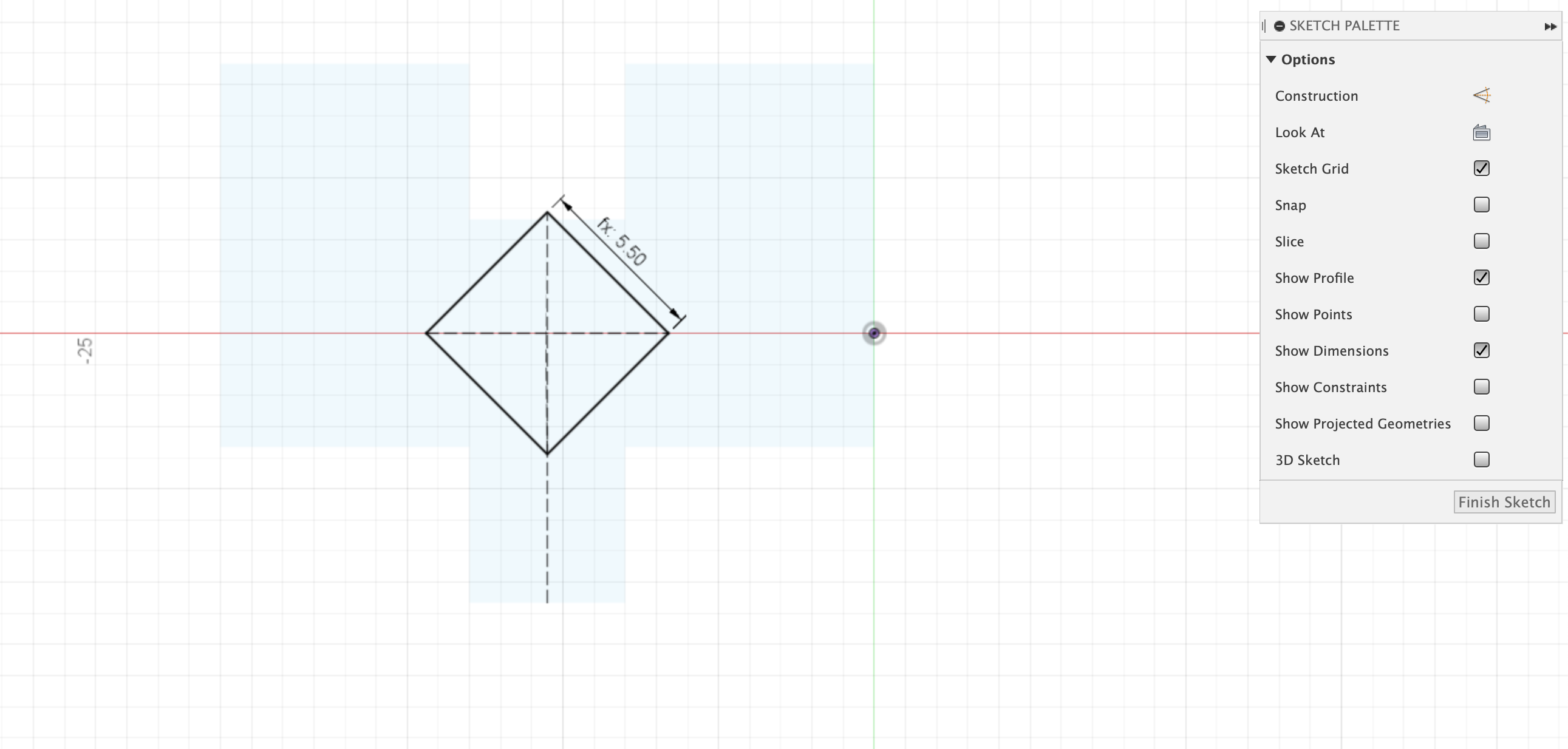
Diamond Profile
The diamond profile is created next as a new sketch on the top of the track body. The diamond is a simple 5.5mm by 5.5mm square that is aligned to the center-line of the main body. It is also perfectly centered, top to bottom and left to right.
Dimensions:
- Diamond_size = 5.5mm
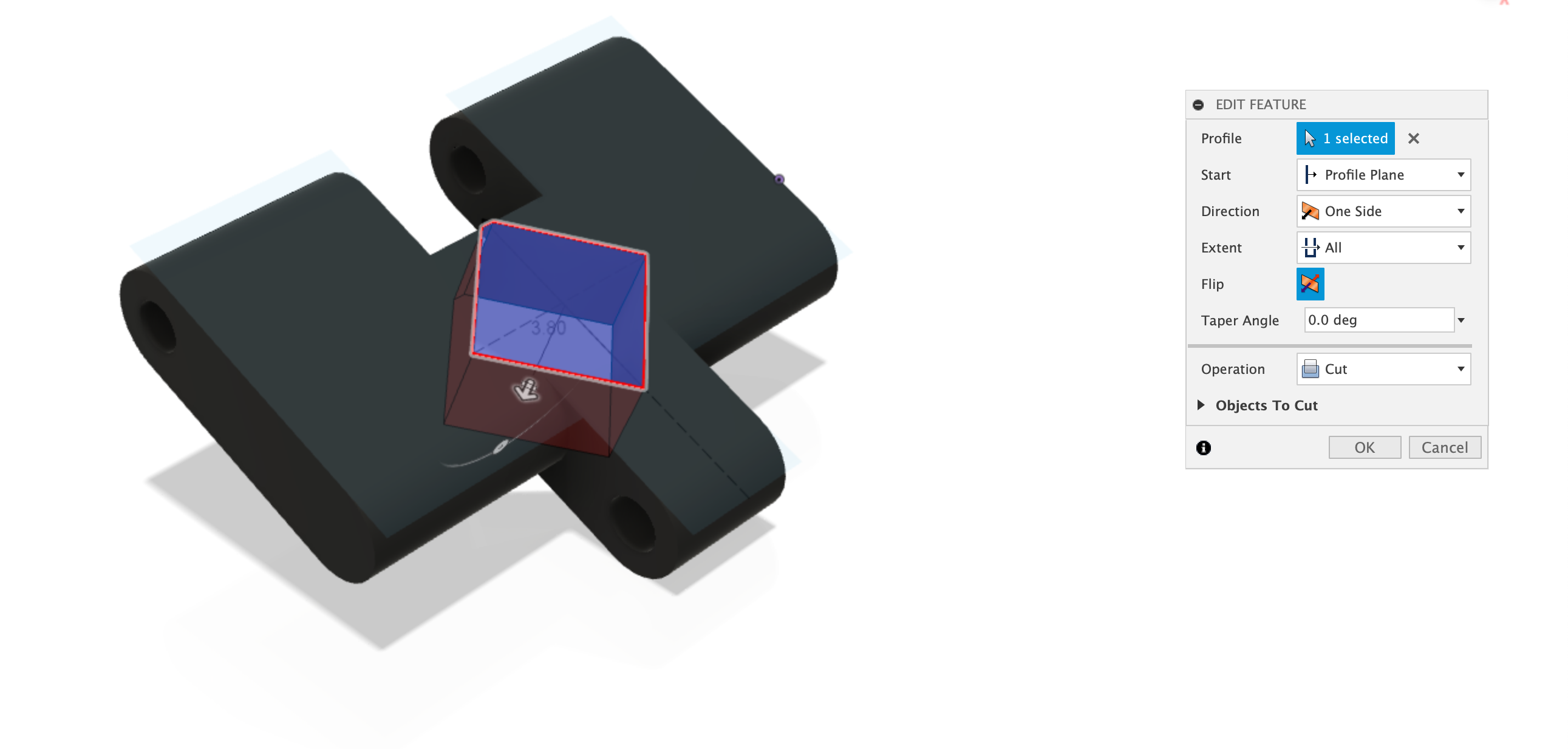
Extrude-cut the Diamond
The diamond profile is now extrude-cut into the body, all the way through.
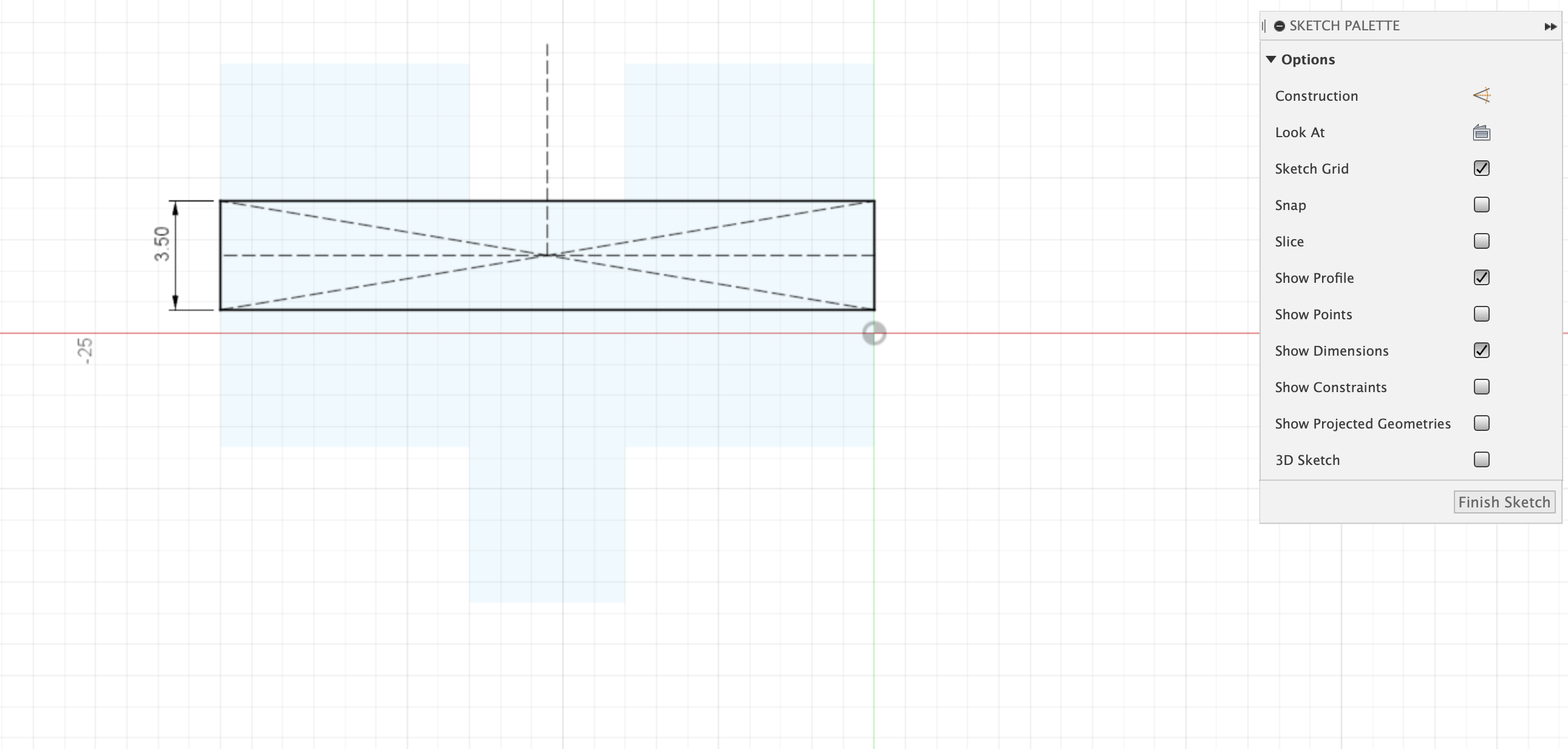
Track Grip profile
The Track Grip profile is created next as a new sketck on the top of the track body. This consists of a simple rectangle.
Dimensions:
- Track_Height = 3.5mm
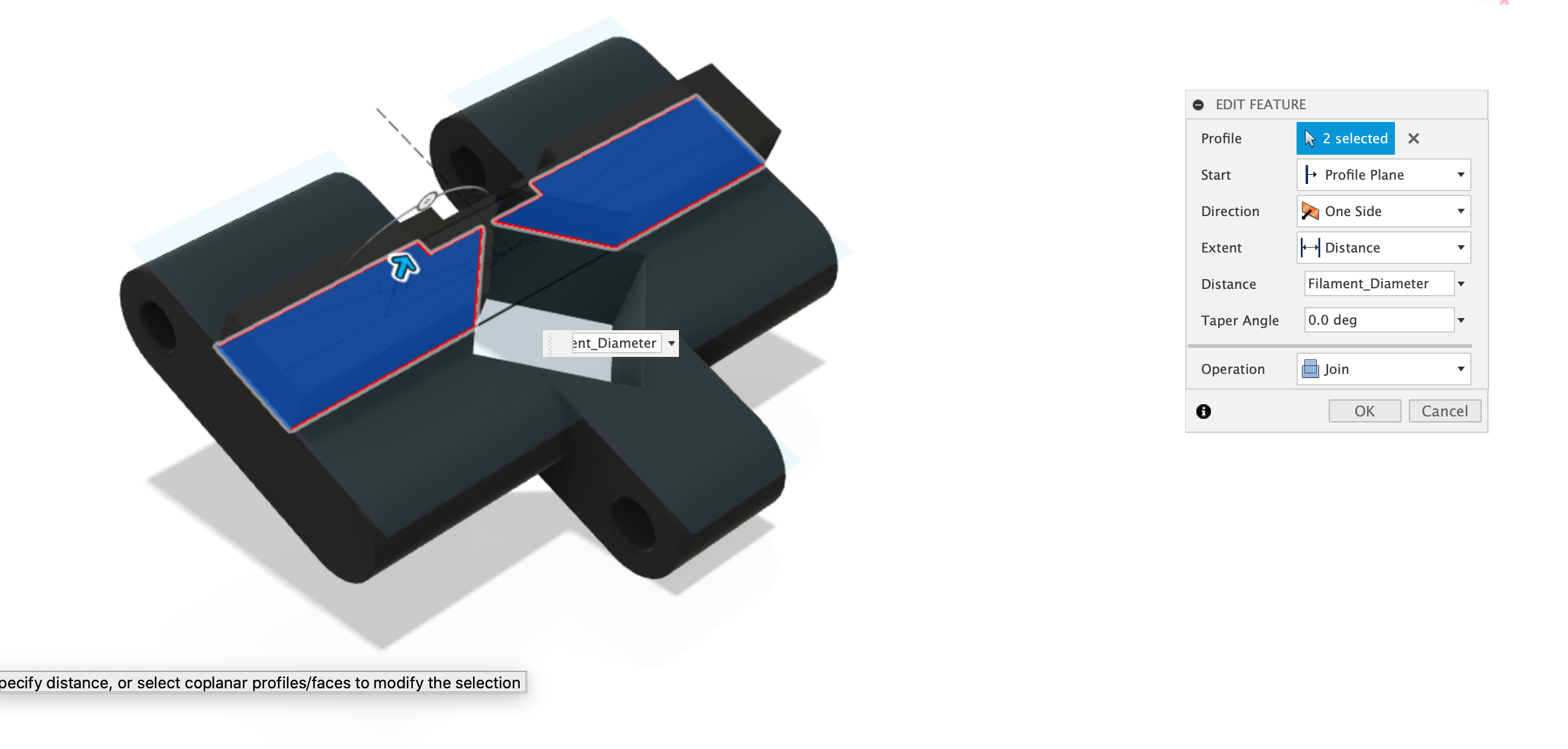
Extrude Track Grip Profile
The Track Grip Profile is now extruded up by the Track_Diameter (3.8mm)
Dimensions:
- Track_Diameter = 3.8mm
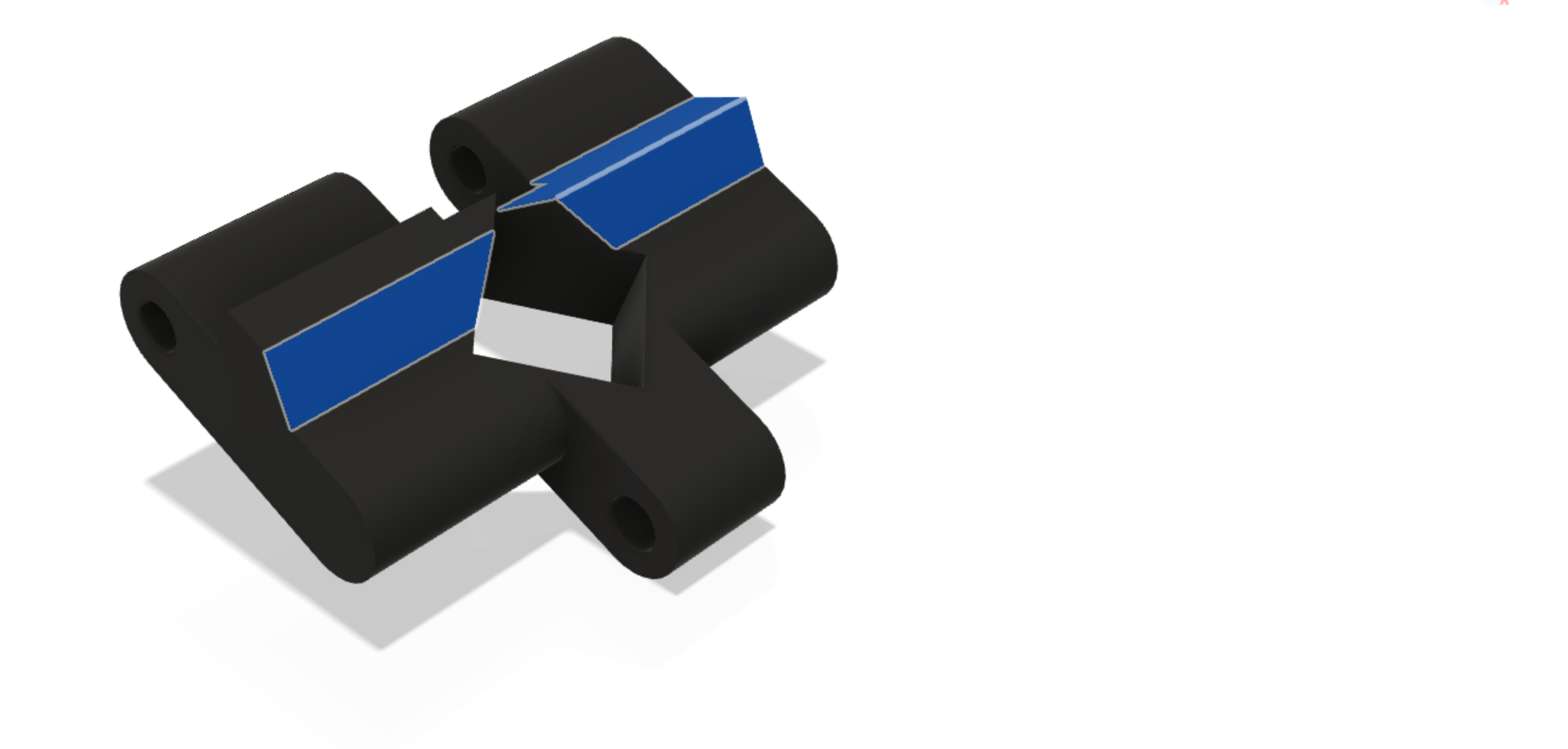
Apply Chamfer to Track Grip
Now apply a chamfer to the newly extruded Track Grip.
Dimensions:
- Fillet = 1.75mm
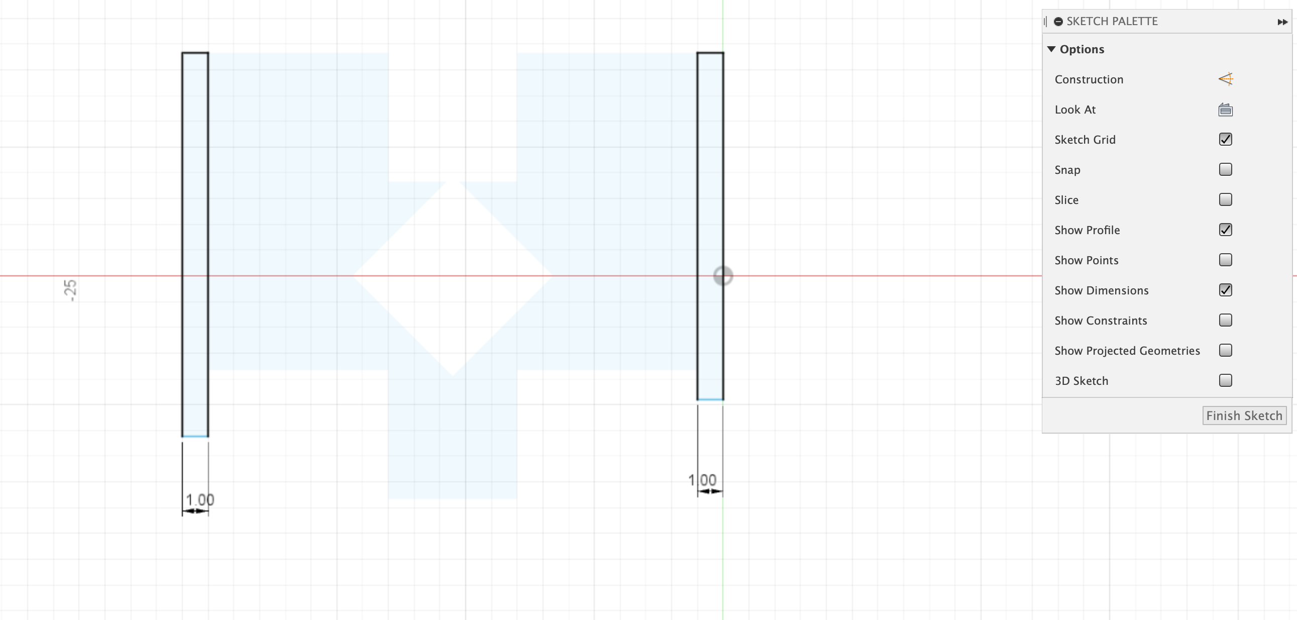
Edge Profile
The Track needs to be trimmed by 1mm on each edge to make it fit between the wheel rims. To do this we need to create a final sketch on the top of the body. Then we simply need to create two rectangled, from top to bottom, aligned with each edge and 1mm in width.
Dimensions:
- width = 1mm
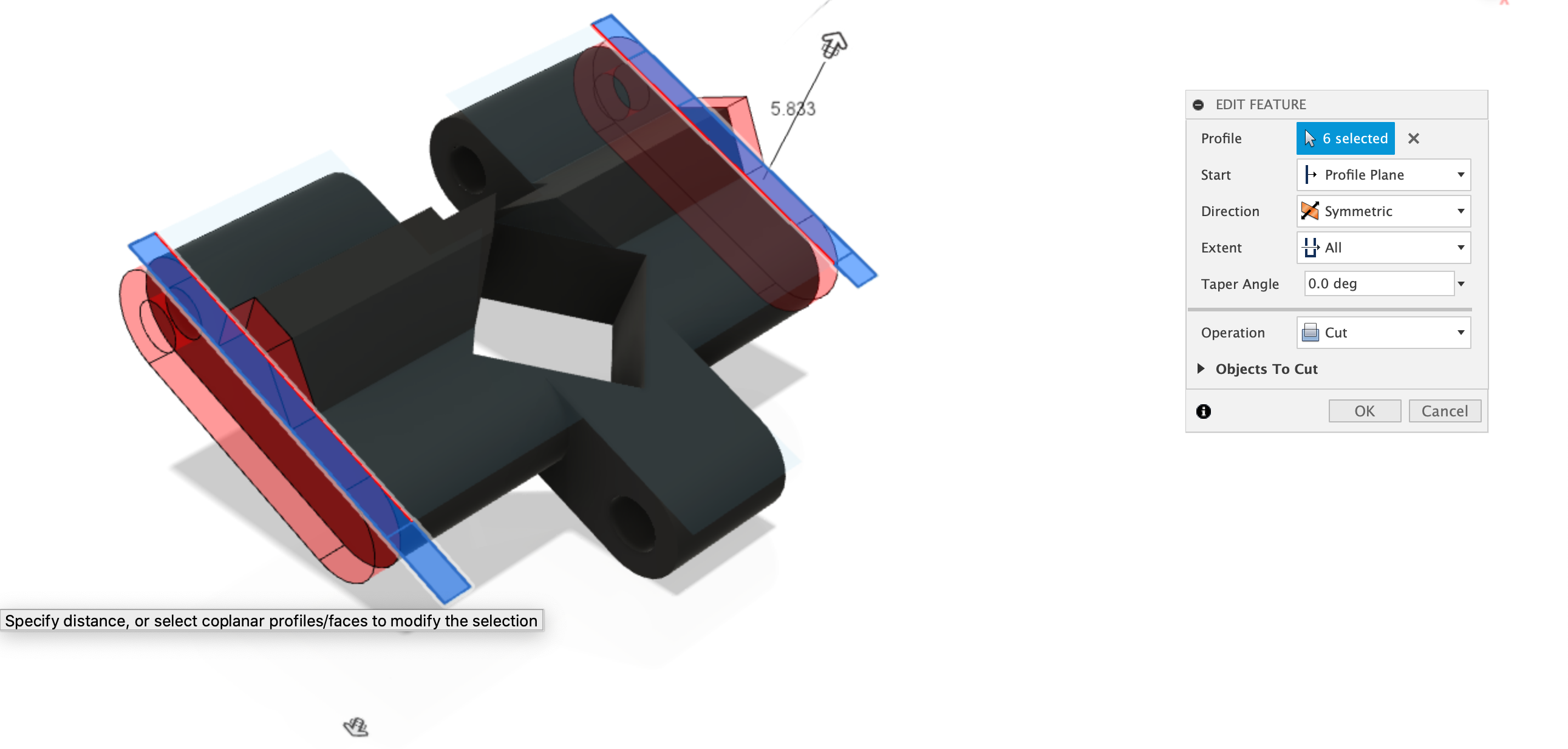
Extrude-Cut the Edges
Use the profile created in the step above to extrude-cut down, all the way through, into the body and trim away 1mm from each edge. The cut needs to be in both directions, as its cutting upward as well as downwards.
Save the STL and Print!
Congratulations, you’ve now created a single piece of caterpillar track that can be printed out and used to give the SMARS more grip on most surfaces. Right-click on the body and select Save STL, then slice it in your favourite slicing software and print out 32 of these, 16 for each side.