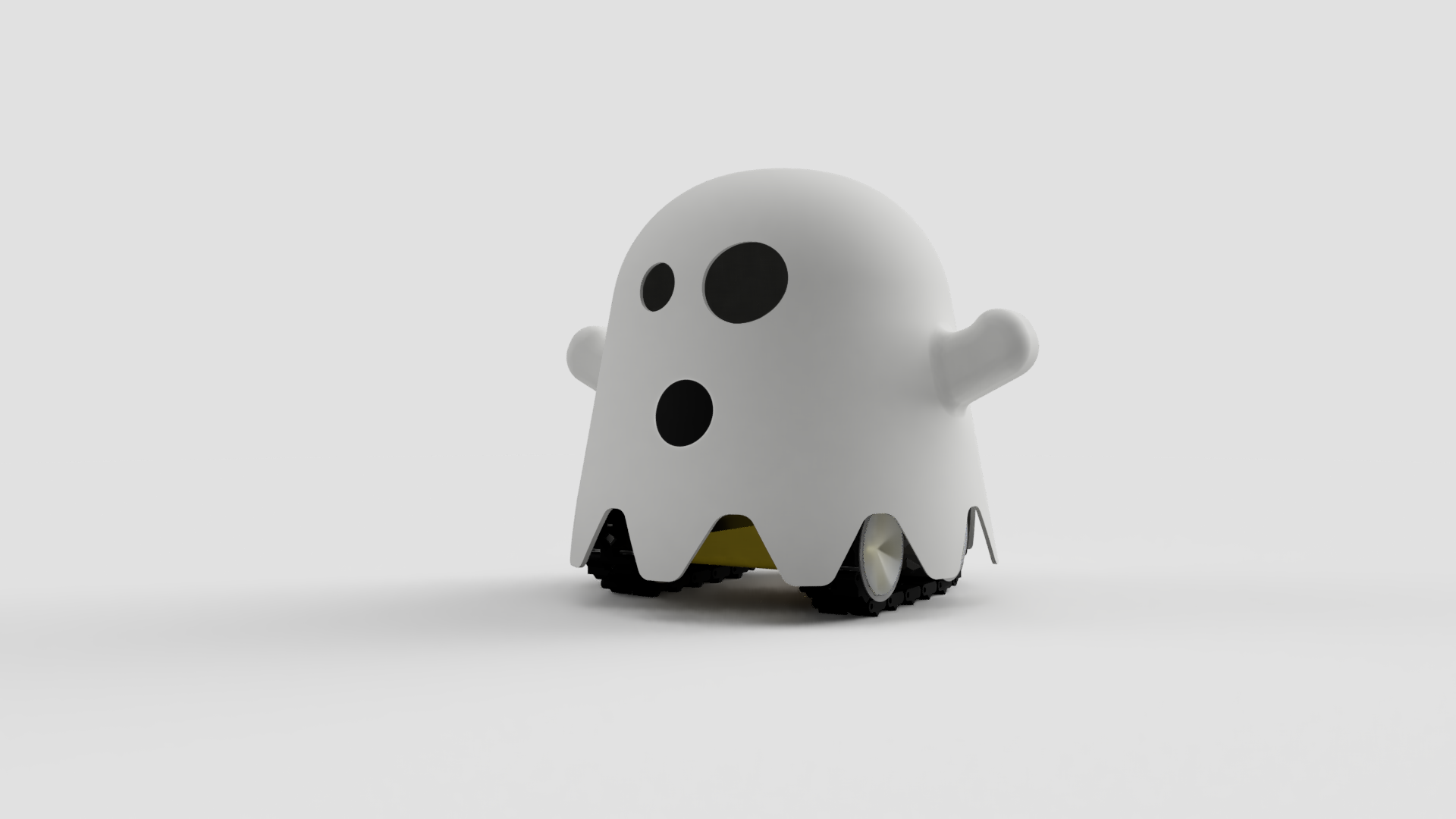
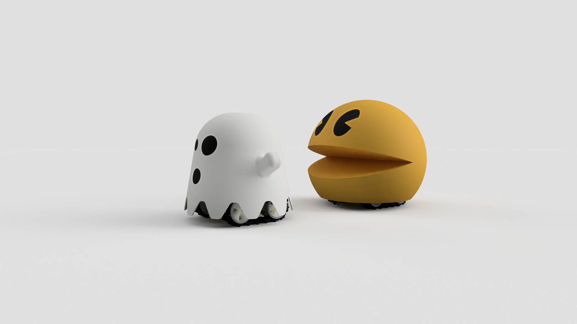
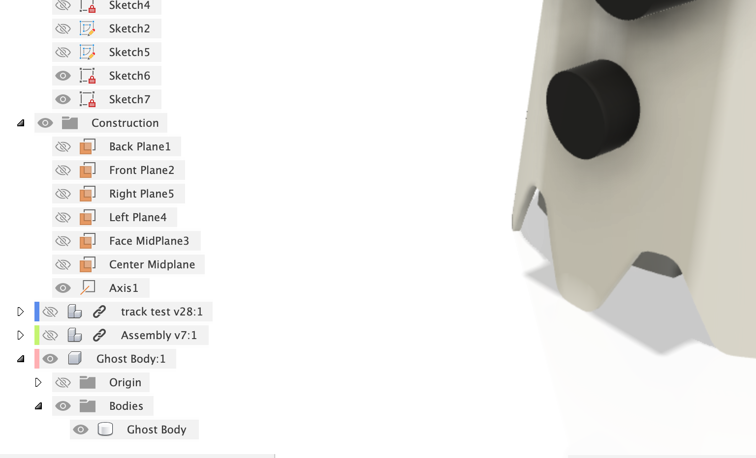
👻 SMARS Ghost
A Cute Ghost Robot using SMARS
Follow these instructions to create your own SMARS Ghost robot

SMARS Ghost
- SMARS Ghost
- Create a new Fusion 360 file
- Download the SMARS Robot
- Insert into Current Design
- Create a new Sketch
- Extrude up and Taper
- Fillet the top
- Shell body
- Create another sketch on the bottom plane
- Extrude the box
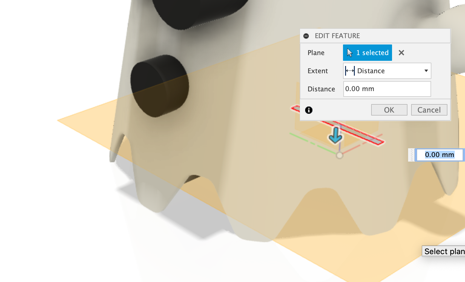
- Create an offset plane
- Create 3 other offset plans
- Create a mid plane
- Create another mid plane
- Create a new sketch using the Face Midplane
- Extrude the hand
- Fillet the hand edges
- Fillet the hand edges (Arm Pit)
- Mirror the hand
- Create a new sketch
- Draw the face
- Draw the Ghosts Skirt
- Extrude Cut the Skirt into the ghost body
- Create an Axis
- Create a new sketch on the bottom face
- Extrude the Mouth and Eyes
- Extrude the Connector
- Pull the face of the Connector
- Extrude the connector to the body
- Create a circular pattern
- Create component from Body
- Create a new sketch
- Extrude Cut the Skirt
- Join the connector to the ghost body
- Slice the ghost for easier 3d printing - Create 4 offset planes
- Combine (Intersect) the Eye with the body
- Combine (Cut) the Eye with the body
- Cut the body up into segments for 3d Printing
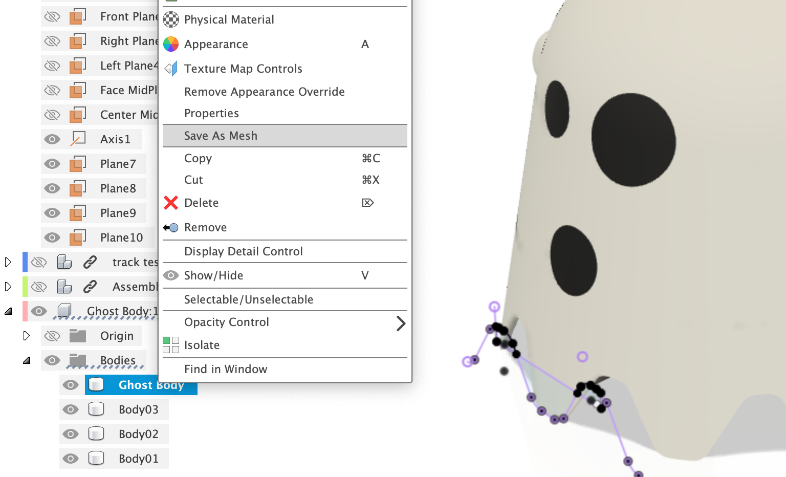
- Appearance
- Export as Mesh (STL)
Create a new Fusion 360 file
Save the new file as SMARS Ghost. We can now import into our current design the SMARS robot - this will help us measure the distances and key measurements to build our new body around.
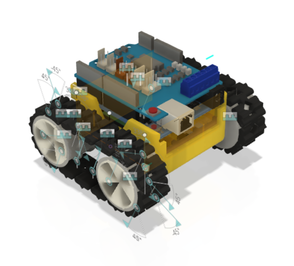
Download the SMARS Robot
To download the SMARS robot - goto grabcad and grab the model file.
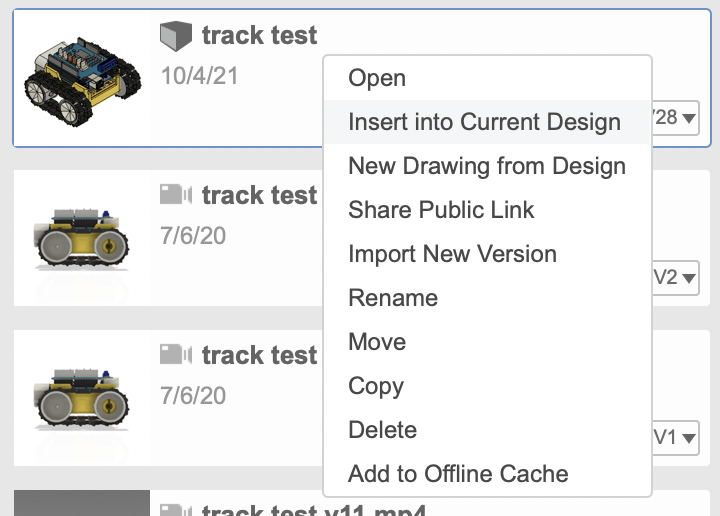
Insert into Current Design
From the Data Panel, right click on the SMARS robot and select Insert into Current Design.
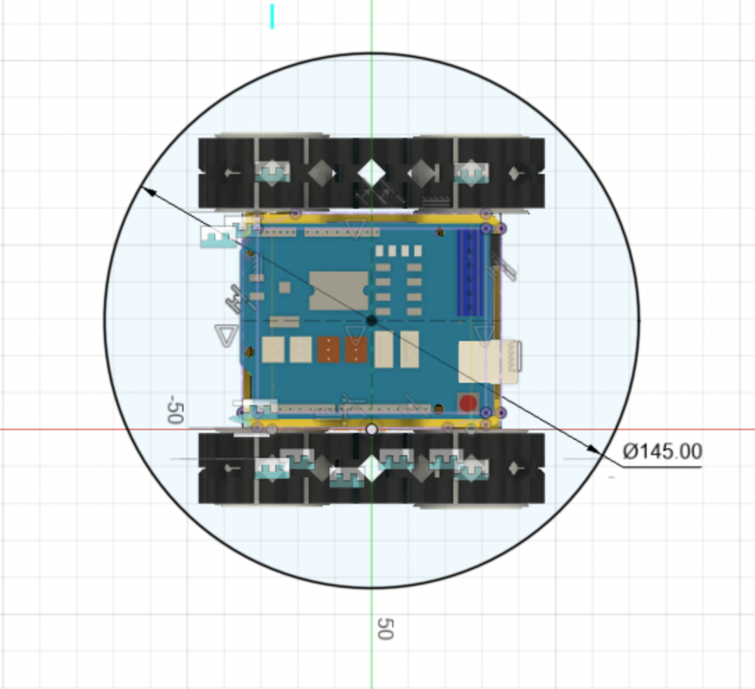
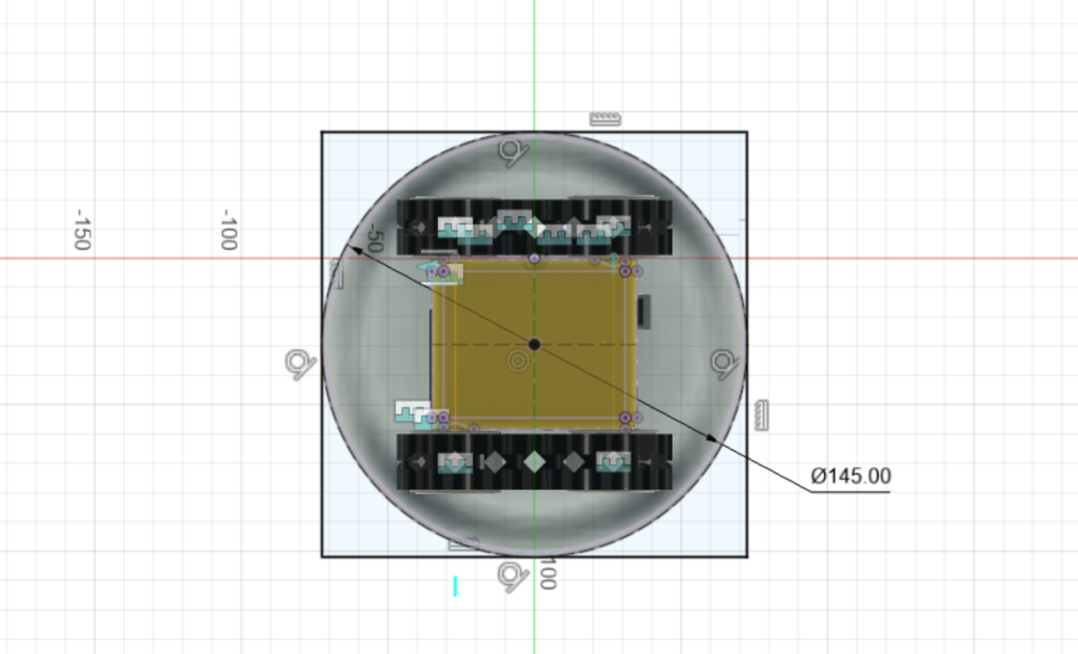
Create a new Sketch
Create a new sketch on the TOP orientation.
Create a circle using the middle of the SMARS as the origin. Make the Circle diameter 145mm. Finish the sketch.
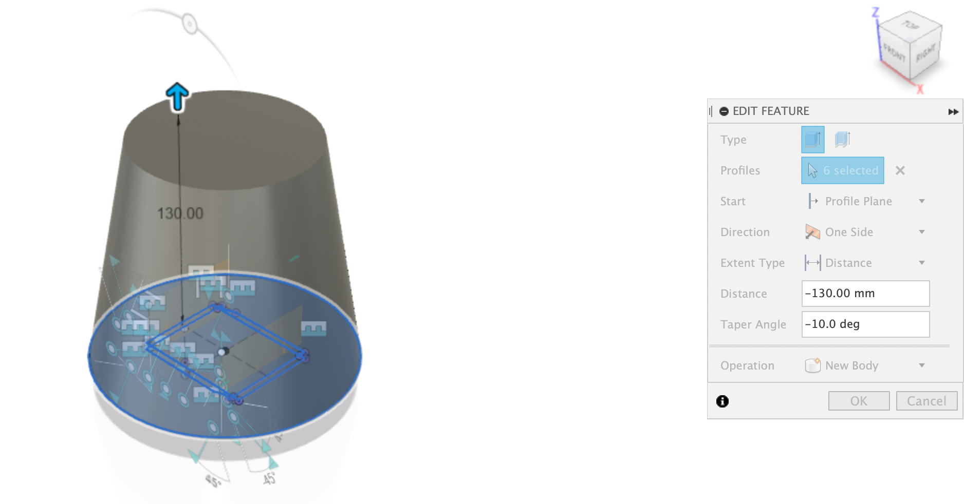
Extrude up and Taper
Extrude the circle up by 130 mm, and taper by -10 degrees. This will create a shape a bit like an upside down plant pot.
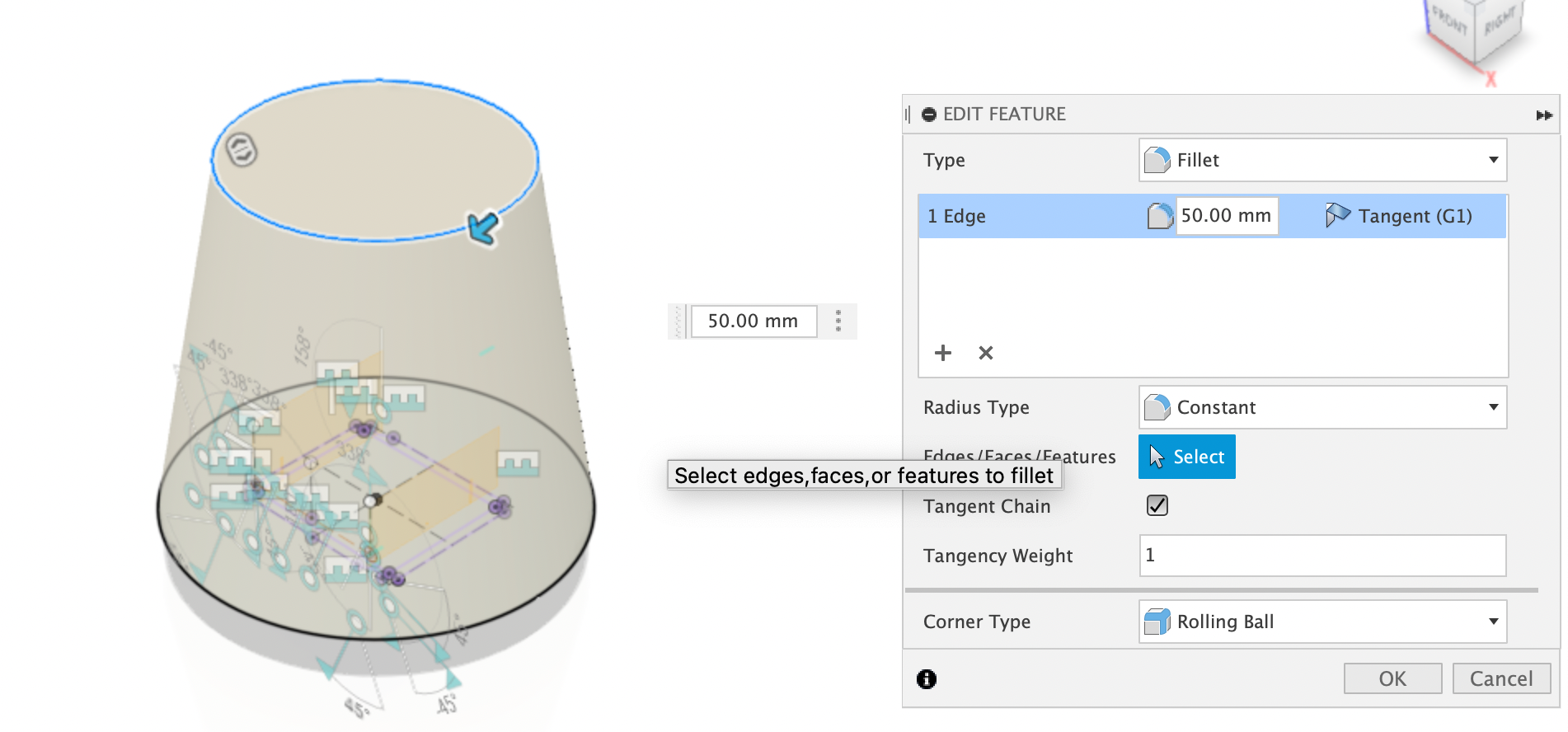
Fillet the top
Fillet the Top edge by 50mm, this will create the ghosts head shape, and should be completely round.
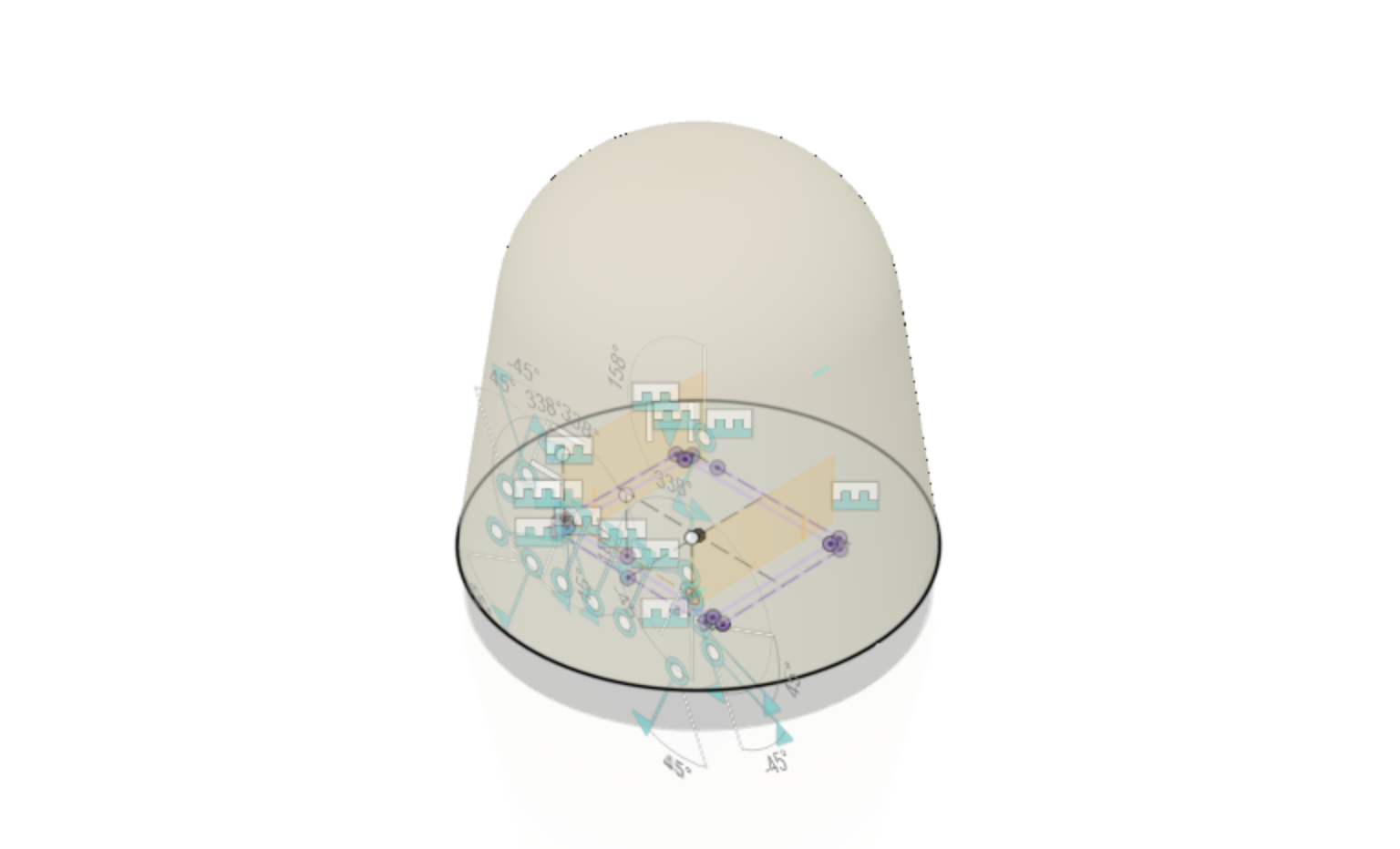
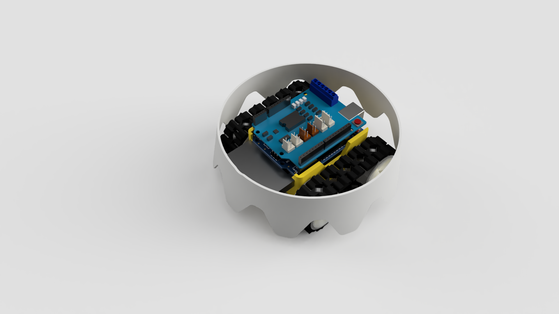
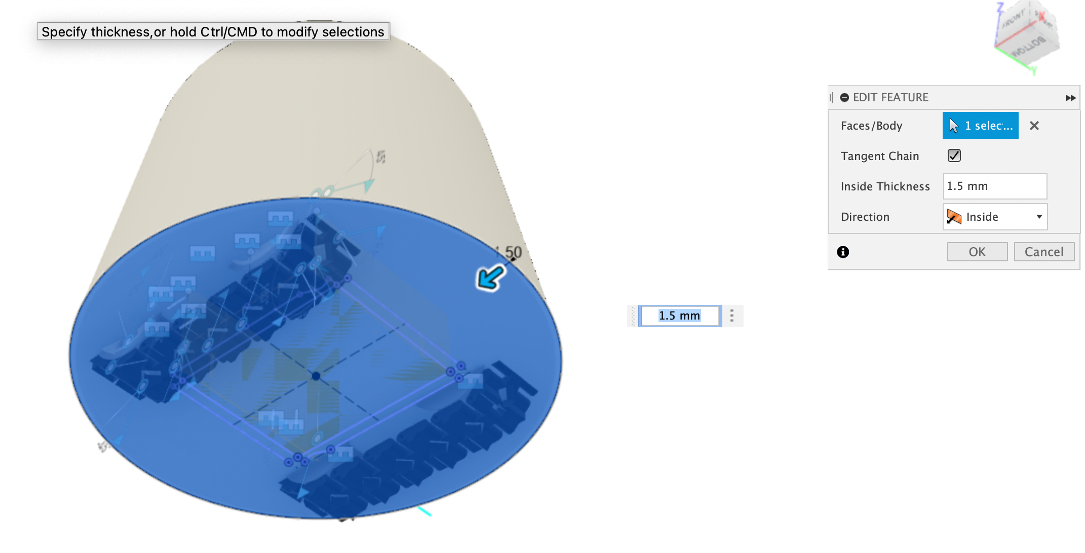
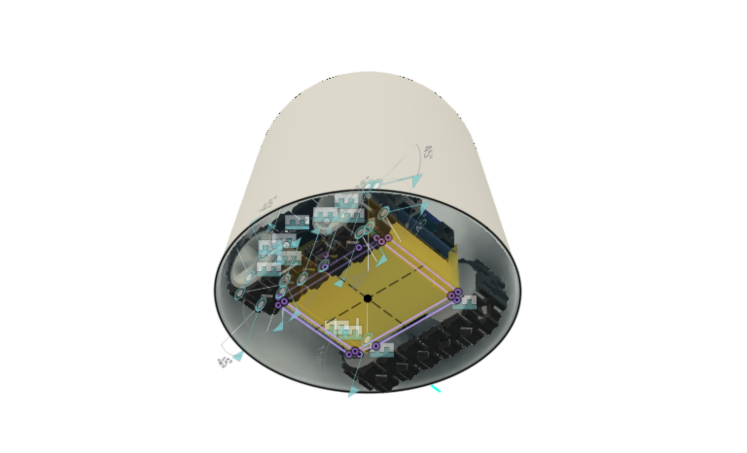
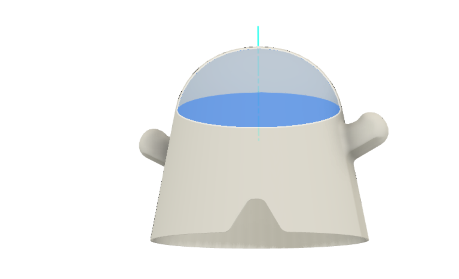
Shell body
Use the shell command to create a thin 1.5mm shell inside the body, by selecting the bottom face. You should be able to see the SMARS robot now inside the Ghost body.
Create another sketch on the bottom plane
Create another sketch on the bottom plane, and project the bottom circle onto it. Then, draw a rectangle and make all the sides tangent to the outside of the Circle. We will use this to create a box that emcompasses the ghost, which will enable us to create a couple of construction planes.
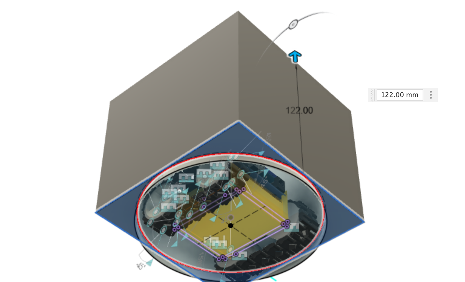
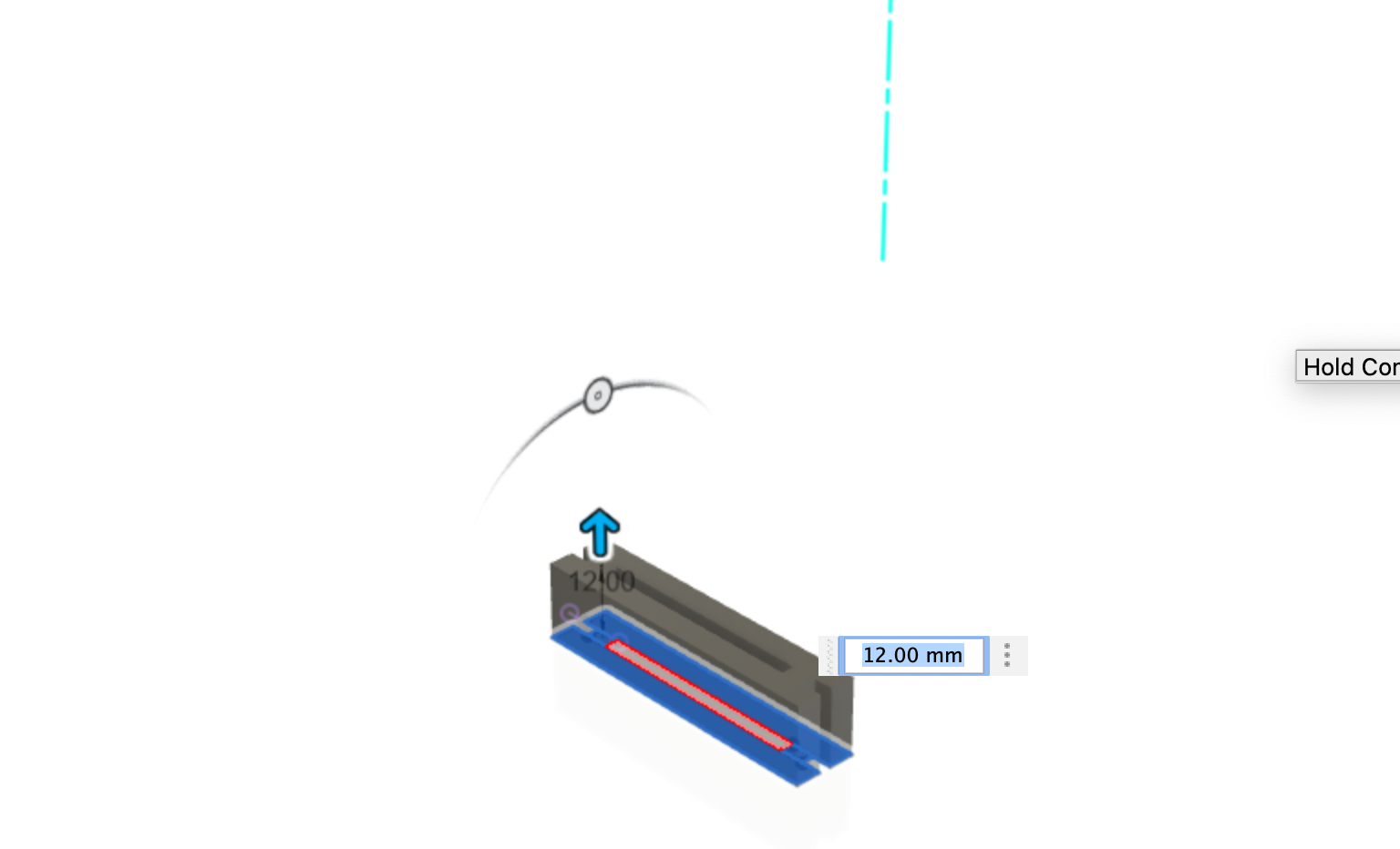
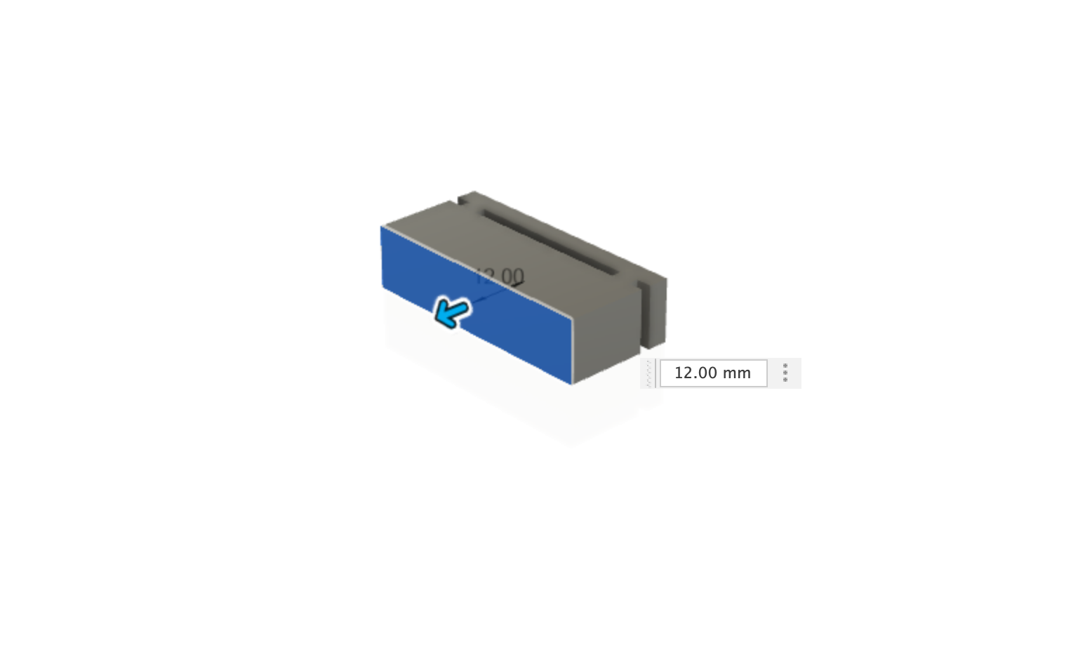
Extrude the box
Extrude the box profile up by 122 mm as a new body.
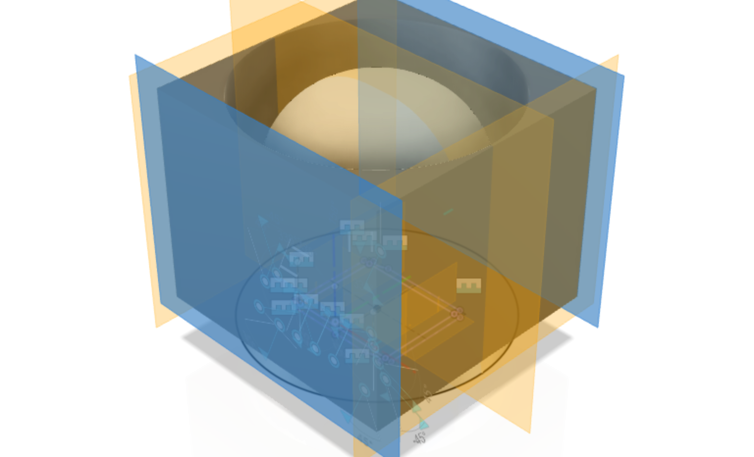
Create an offset plane
Create a new offset plane, from the back of the box and name it Back Plane in the browser.
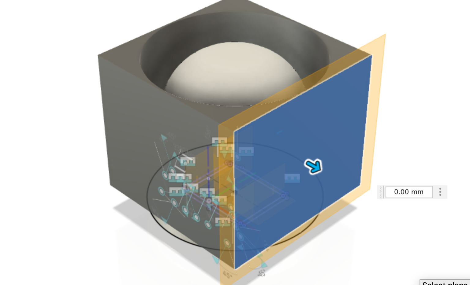
Create 3 other offset plans
Like the step above, create 3 other offset plane for each of the sides and name in them in the browser:
front planeleft side planeright side plane
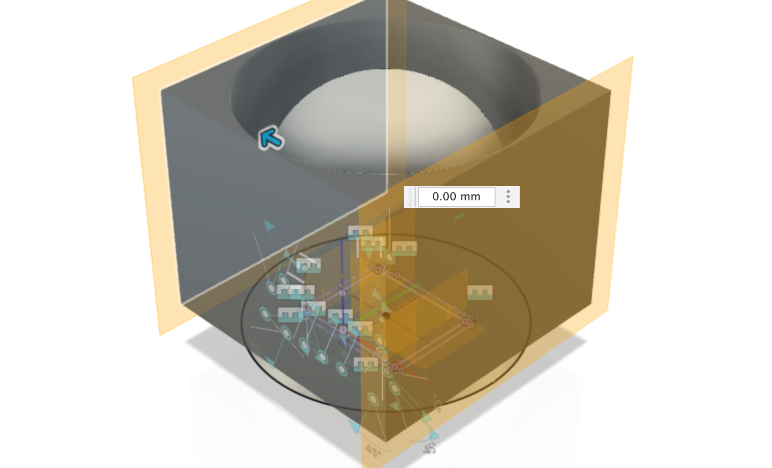
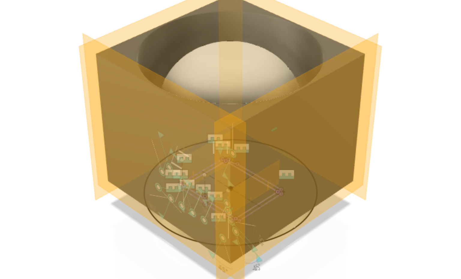
Create a mid plane
Using the front and back construction planes create a new mid plane. Rename this in the browser to be center midplane.
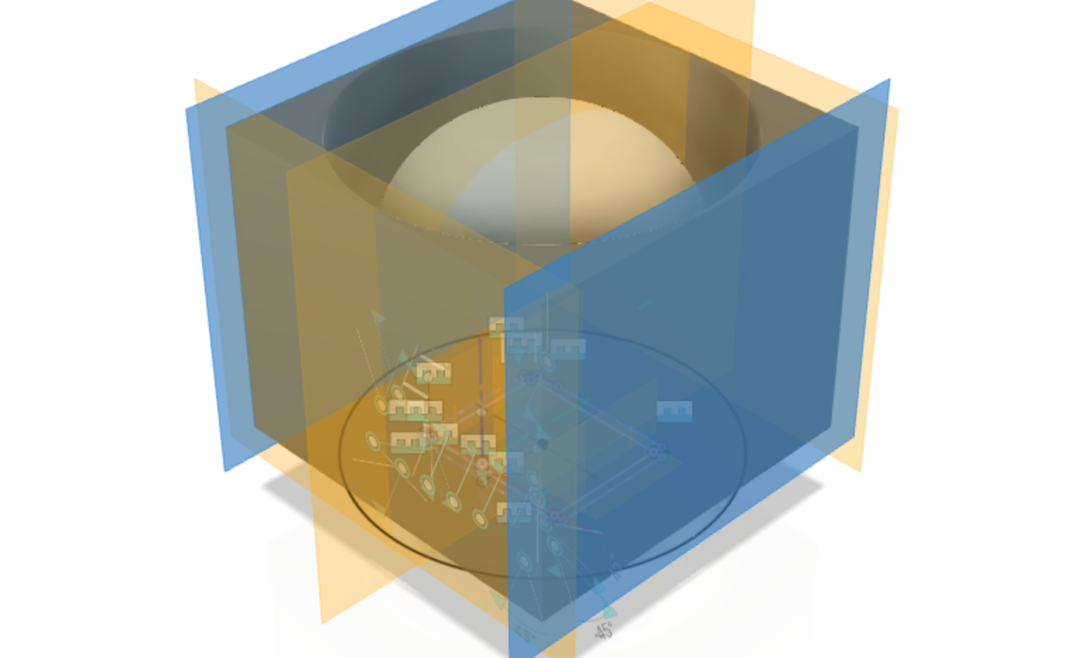
Create another mid plane
Using the left and right construction planes create a new mid plane. Rename this in the browser to be Face midplane.
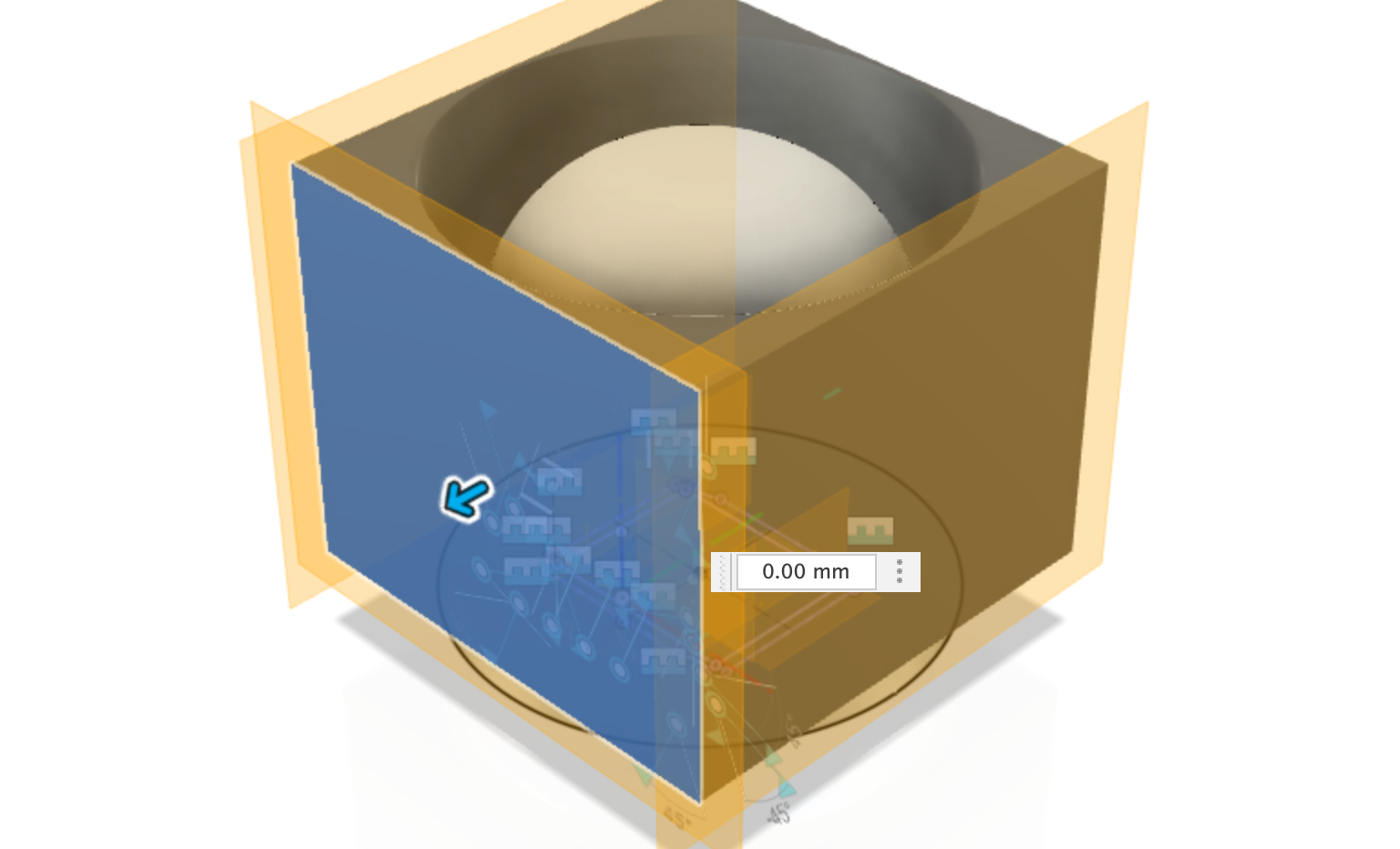
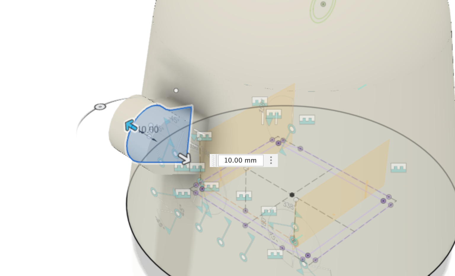
Create a new sketch using the Face Midplane
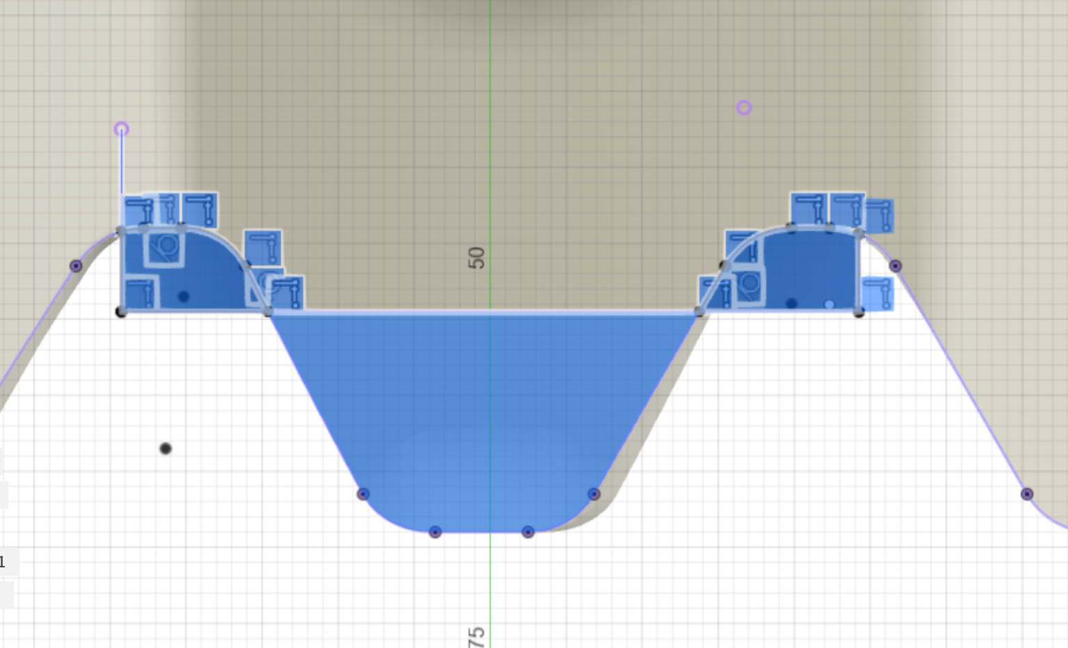
Create a new sketch using the Face Midplane. This is the Ghosts hand.
Sketch out the shape of the ghosts hand. I did this by creating a rought rectangular shape and then adding some fillets to each corner.
See the diagram below for the freehand lines I drew (I’ve added dimensions to the diagram just in case you want to make an exact replica).
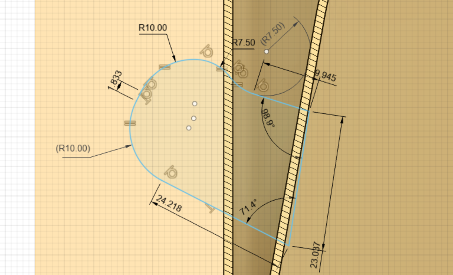
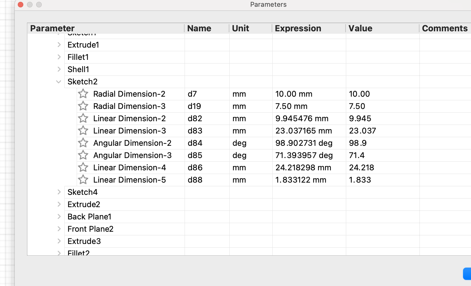
| Parameter | Name | Unit | Expression | Value | Comments |
|---|---|---|---|---|---|
| Radial dimension-2 | d7 | mm | 10.00mm | 10.00 | |
| Radial dimension-3 | d19 | mm | 7.5mm | 7.50 | |
| Linear dimension-2 | d82 | mm | 9.945476 | 9.945 | |
| Linear dimension-3 | d83 | mm | 23.037165 | 23.937 | |
| Angular dimension-2 | d84 | deg | 98.902731 | 98.9 | |
| Angular dimension-3 | d85 | deg | 71.393957 | 71.4 | |
| Linear dimension-4 | d86 | mm | 24.218298 | 24.218 | |
| Linear dimension-5 | d88 | mm | 1.833122 | 1.833 |
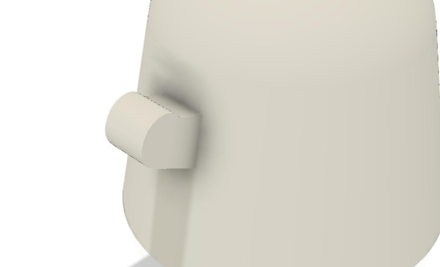
Extrude the hand
Hide the construction planes, and the cube, and make sure the newly created sketch is visible in the browser.
Select the new hand profile and then press q to extrude it out by 10mm, set the Direction to symmetric to extrude it out in both directions, and make sure the operation type is Join.
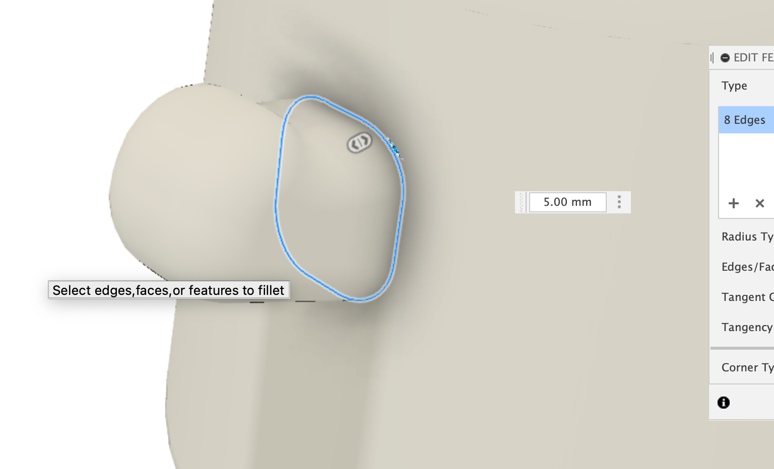
Fillet the hand edges
Using the fillet tool, select the front and back edges of the hand, and then apply a 7mm fillet.
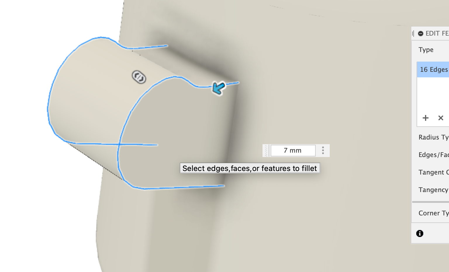
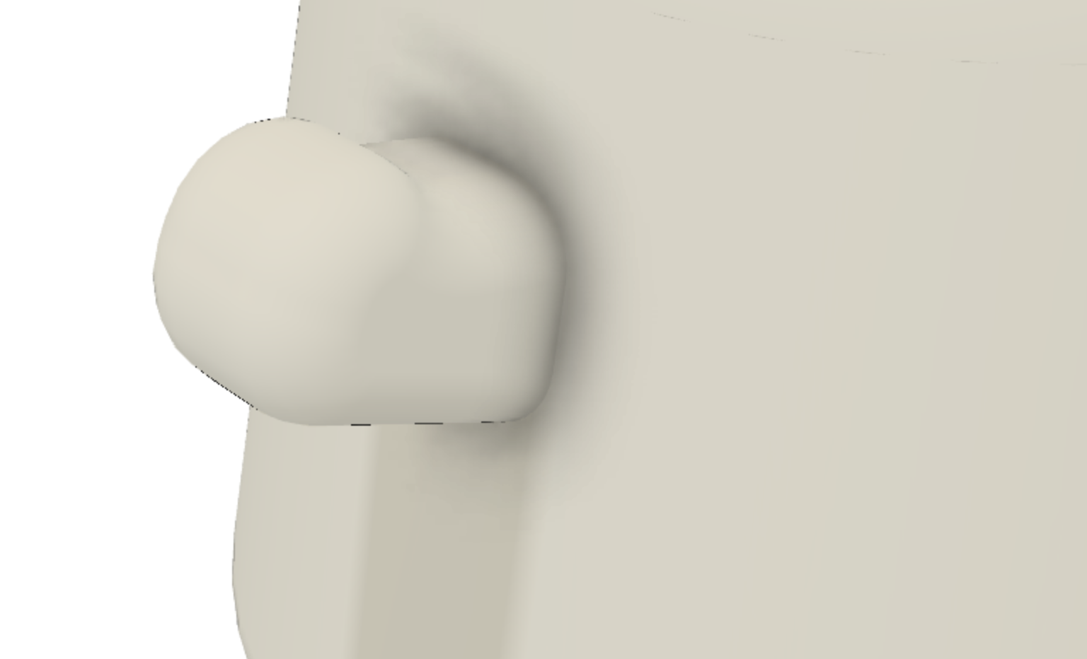
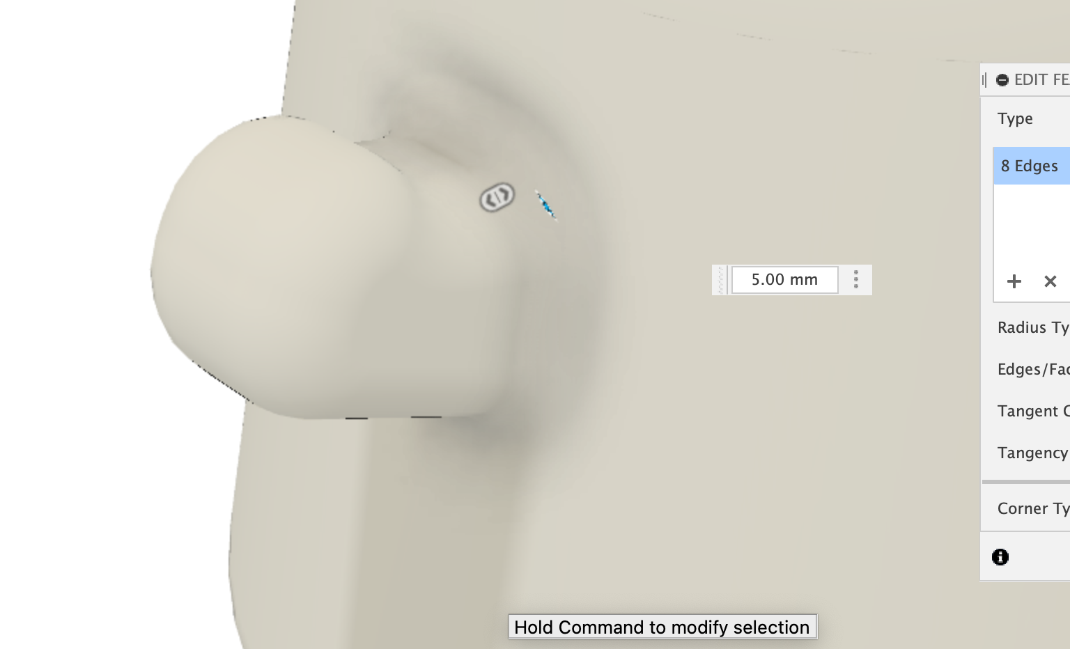
Fillet the hand edges (Arm Pit)
Using the fillet tool, select the part of the hand that connects to the body, and then apply a 5mm fillet.
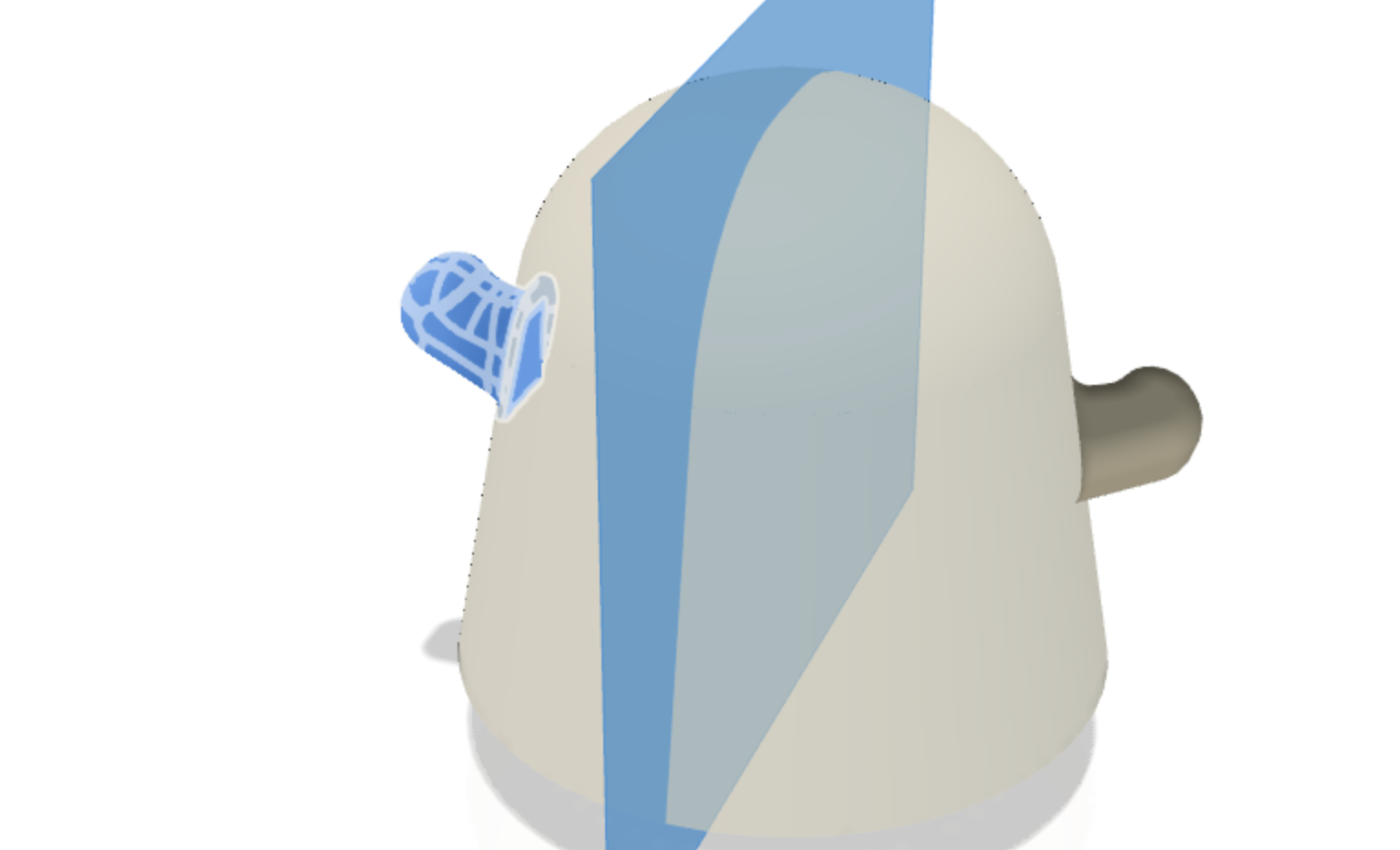
Mirror the hand
From the browser, make the centre mid plane visible, and then select Features from the type option, then the center mid plane as the Mirror Plane, then select the three features from the timeline:
- Extruded Hand
- Hand Fillet
- Armpit Fillet
Create a new sketch
Make the Face Midplane visible from the browser, then create a new sketch on it. We will use this plane to sketch our Ghosts Face.
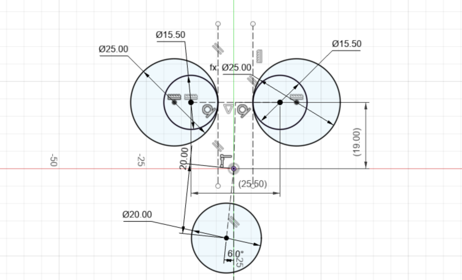
Draw the face
The ghosts face consists of three circles: two for the eyes, and one for the mouth. The Eye circles are 25mm in diameter, with a 15.5mm circle within it, which is tangent to the right and left edge respectively. I’ve used two construction lines to help with the tangent.
The mouth is 20mm in diameter, and is 20mm below the origin point. I’ve used a construction line at a 6 degree angle from the center line to give the mouth a little character.
The eyes are spaced 25.5mm apart, and are 19mm above the origin point.
–
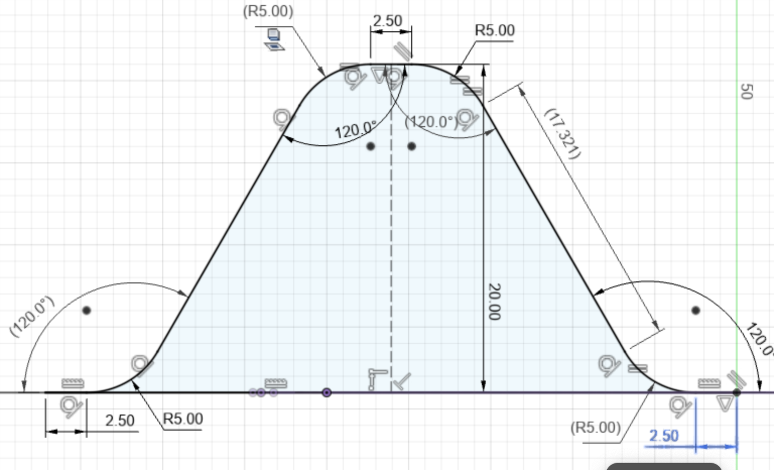
Draw the Ghosts Skirt
Create a new sketch using the front plane (not the front mid plane). We will know draw one sesion of the ghosts skirt and then use a circular pattern to repeat it round our ghost body.
The skirt shape is basically a trapeisum shape, with a couple of filleted corners. The height of the trapesium is 20mm from the bottom of the ghost body. You can use the project command to project in the bottom edge.
The sides of the trapsieum are 17.321mm, with a 120degree angle from the base. The corners are rounded by 5mm. There is a little line at the top and bottom of the trapesium that is 2.50mm in length.
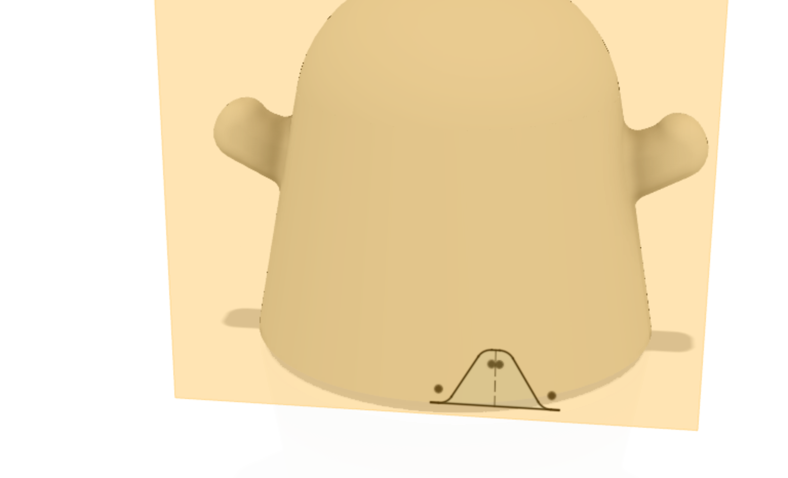
Extrude Cut the Skirt into the ghost body
Extrude Cut the Skirt into the ghost body by 30mm.
Create an Axis
Use the Create Axis command to create a new Axis through the middle of the ghost body; you can use the bottom circle of the ghost body to center the axis.
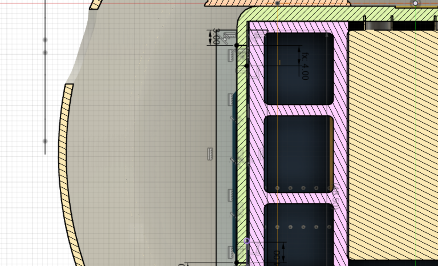
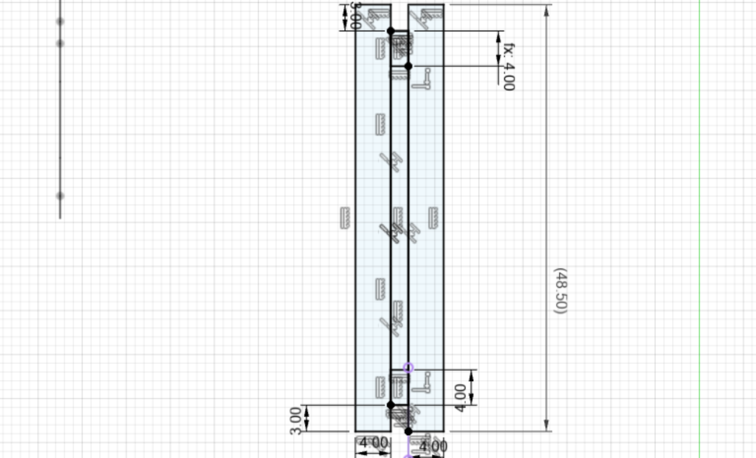
Create a new sketch on the bottom face
Create a new sketch on the bottom face of the ghost body and draw out two rectangles, 4mm by 48.5mm - project in the SMARS robot chassis connector area to ensure this is a perfect fit.
Create another rectable between the first two (3mm by 42.50mm), and then finally create two little rectangles within the middle rectangle at the top and the bottom, 4mm in height.
Extrude the Mouth and Eyes
Select the mouth and eye profiles, and extrude them back from the front plane through the ghost body by 30mm, as a New Body.
Name the new bodies:
Left EyeRight EyeMouth
Extrude the Connector
Extrude the Connector profile by 12mm, we will use this to connect the ghost body to the SMARS robot. Name this new body Connector
Pull the face of the Connector
Press Q to offset the face of the connector that faces the inside of the Ghost body by 12mm. We will use the combin command shortly to cut this then join this to the body.
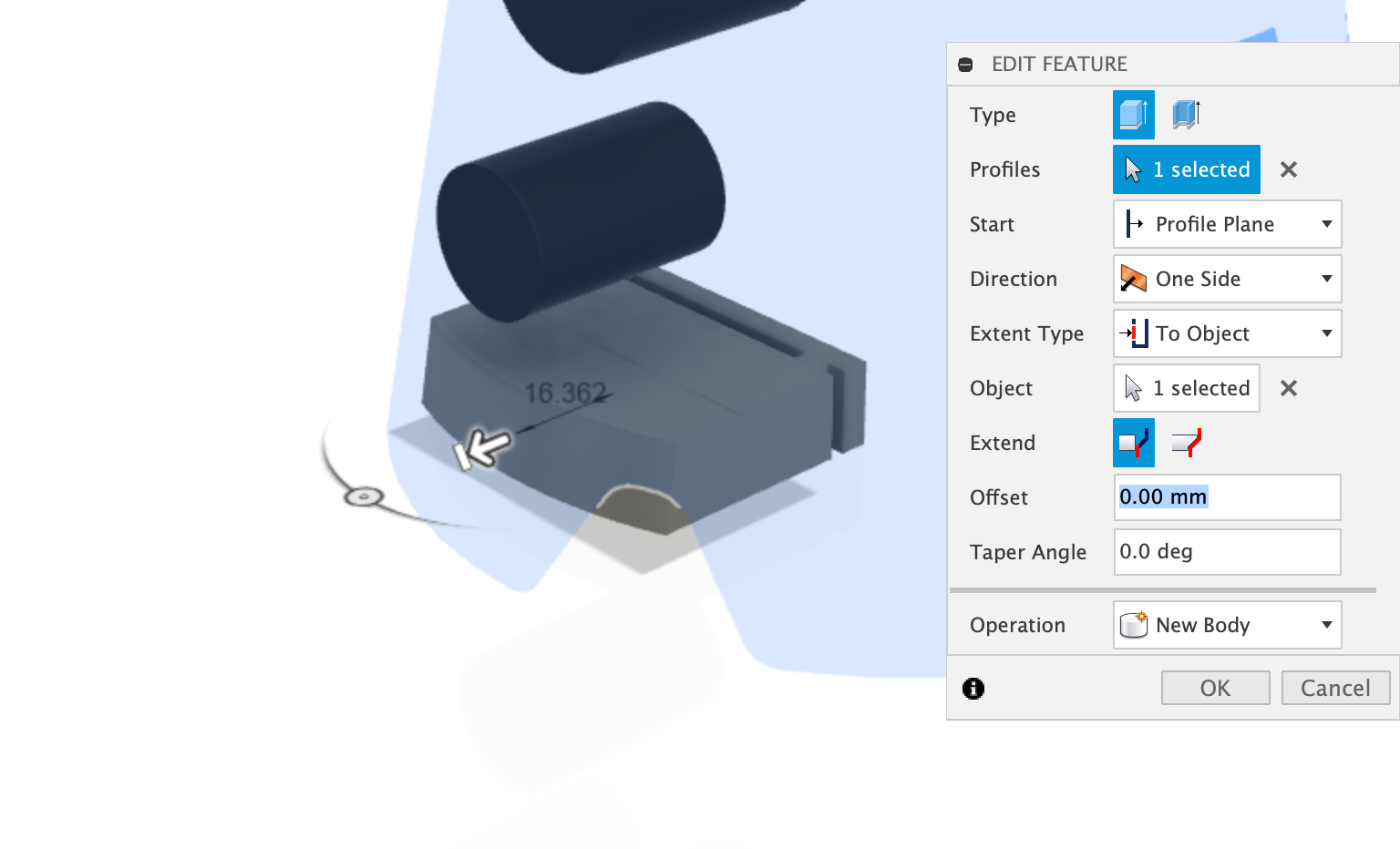
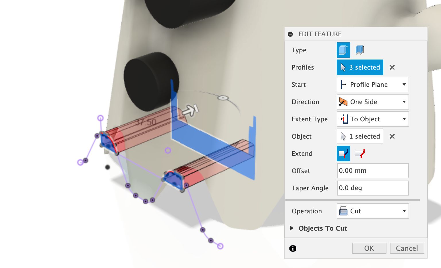
Extrude the connector to the body
Using the extrude command, extrude the same face you have just pulled forward, set the Extent Type to To Object and then select the Object to be the Ghost Body body, ensure the Extend is set to To Selected Face (the first icon).
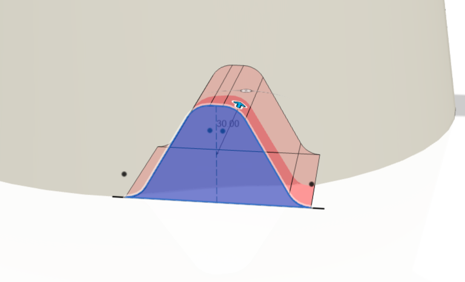
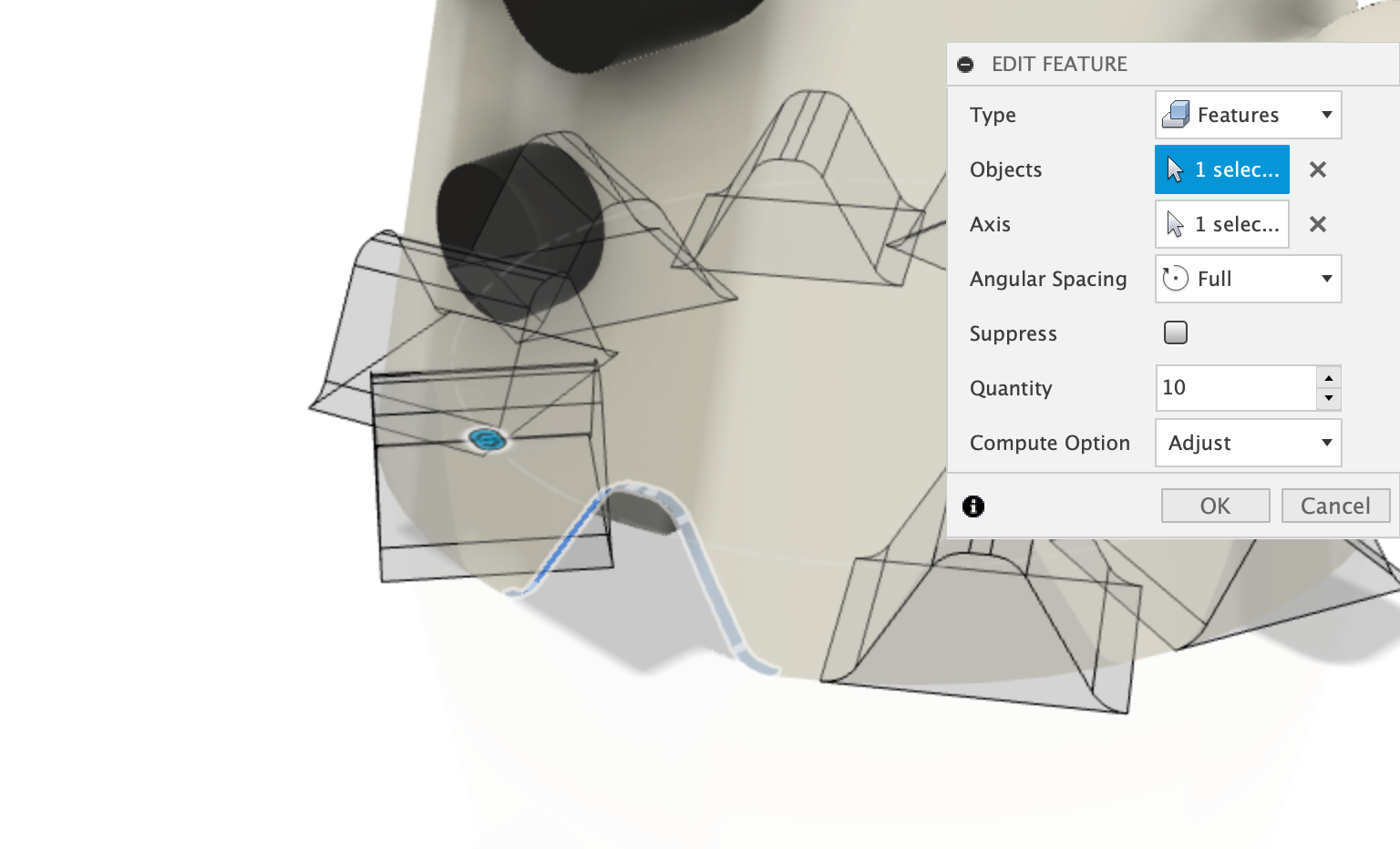
Create a circular pattern
Using the Circular pattern command, select the Extruded Skirt feature from the timeline and the Axis we created, and then set the quantity to 10.
Create component from Body
Select the Ghost Body body from the browser, and then right click on it and select the Create Components from Bodies command. This will promote the body to be a component in the Browser.
Create a new sketch
Create a new sketch on the front face plane, and project in the skirt shape where it over laps the connector body.
We will use this profile to cut out the connector. Make sure the profile is enclosed by using extra lines. The profile will turn blue when it is totally enclosed.
Extrude Cut the Skirt
Select the new profile and extrude cut it back, selecting the Extent Type to Object, and object to be the back of the Connector.
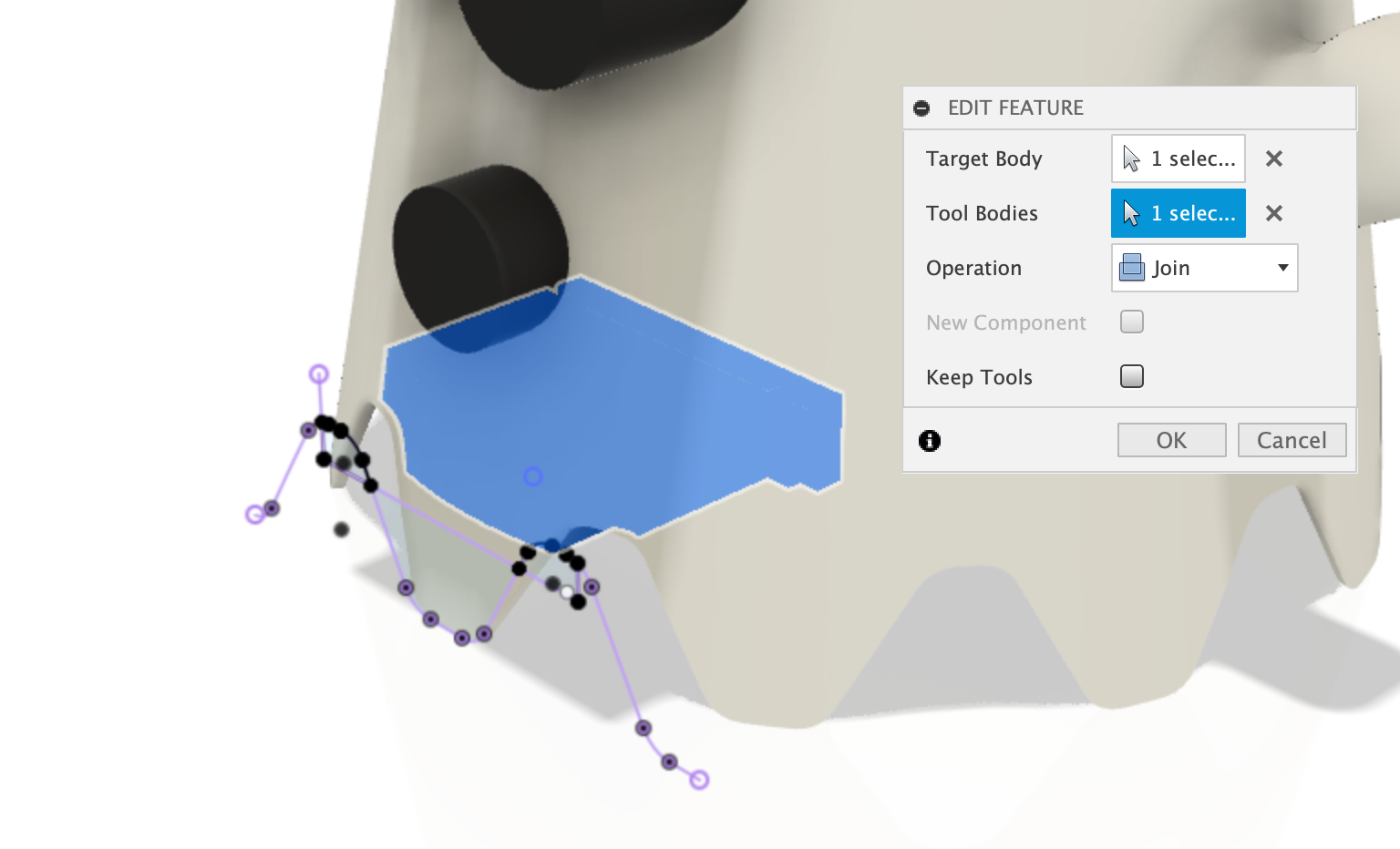
Join the connector to the ghost body
Select the Combine command and select both the Ghost Body and the Connector.
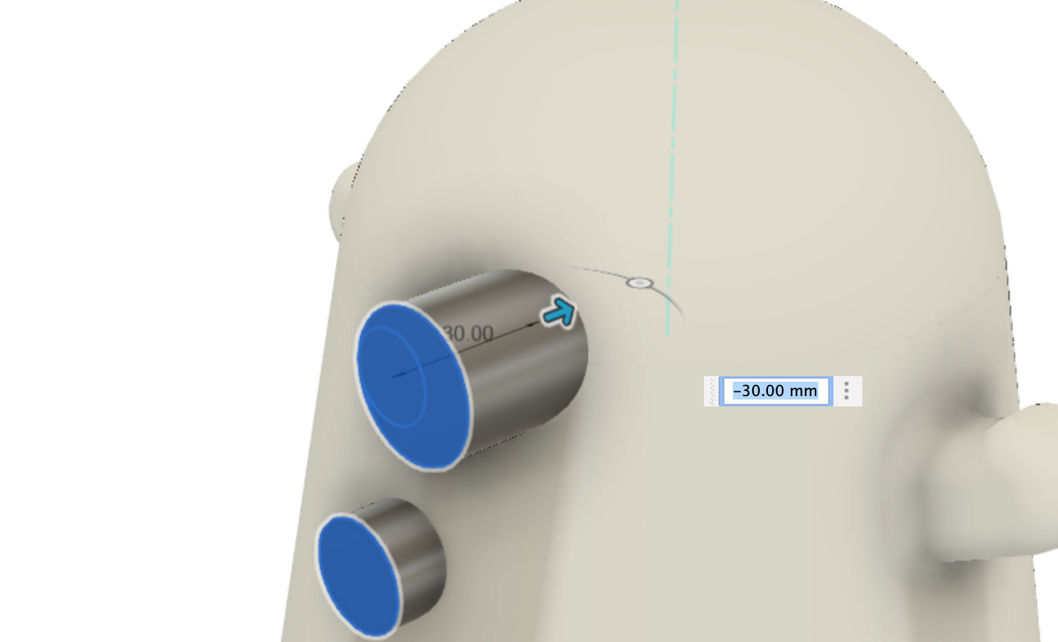
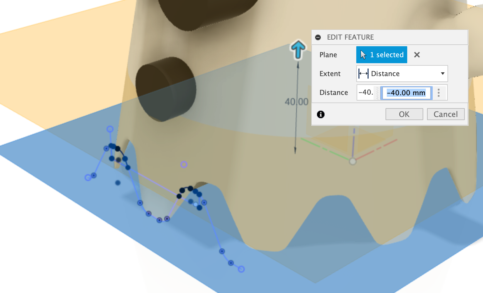
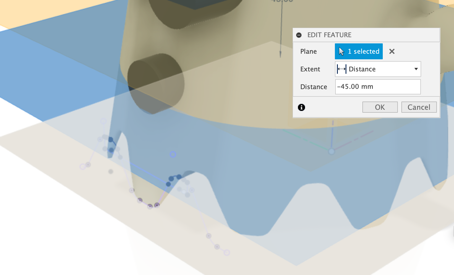
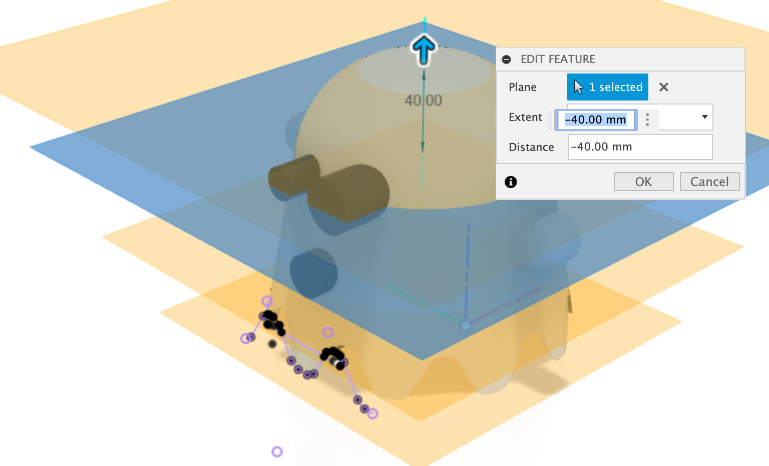
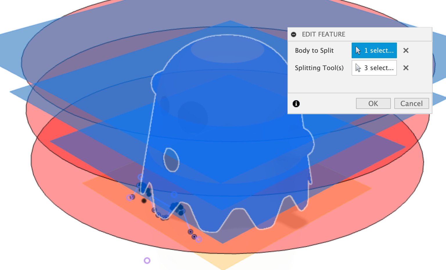
Slice the ghost for easier 3d printing - Create 4 offset planes
Create 4 offset planes:
- 0mm from the bottom face of the ghost
- -40mm from the first offset plane
- -45mm from the second offset plane
- -40mm from the third offset plane
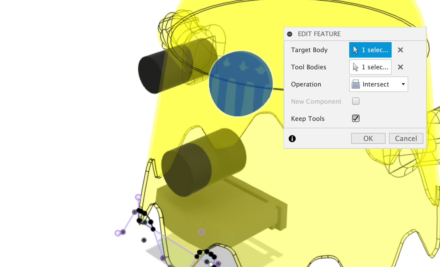
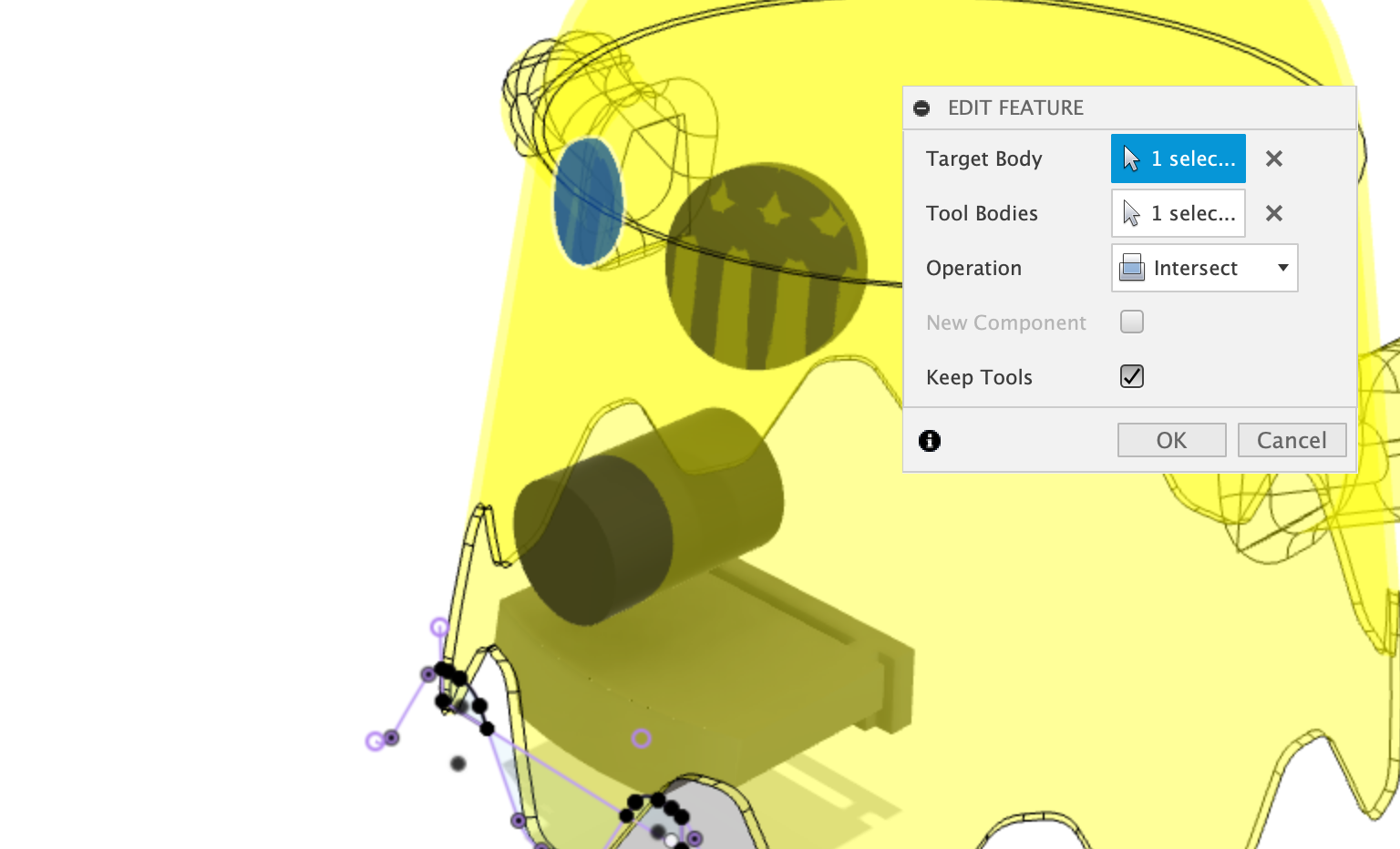
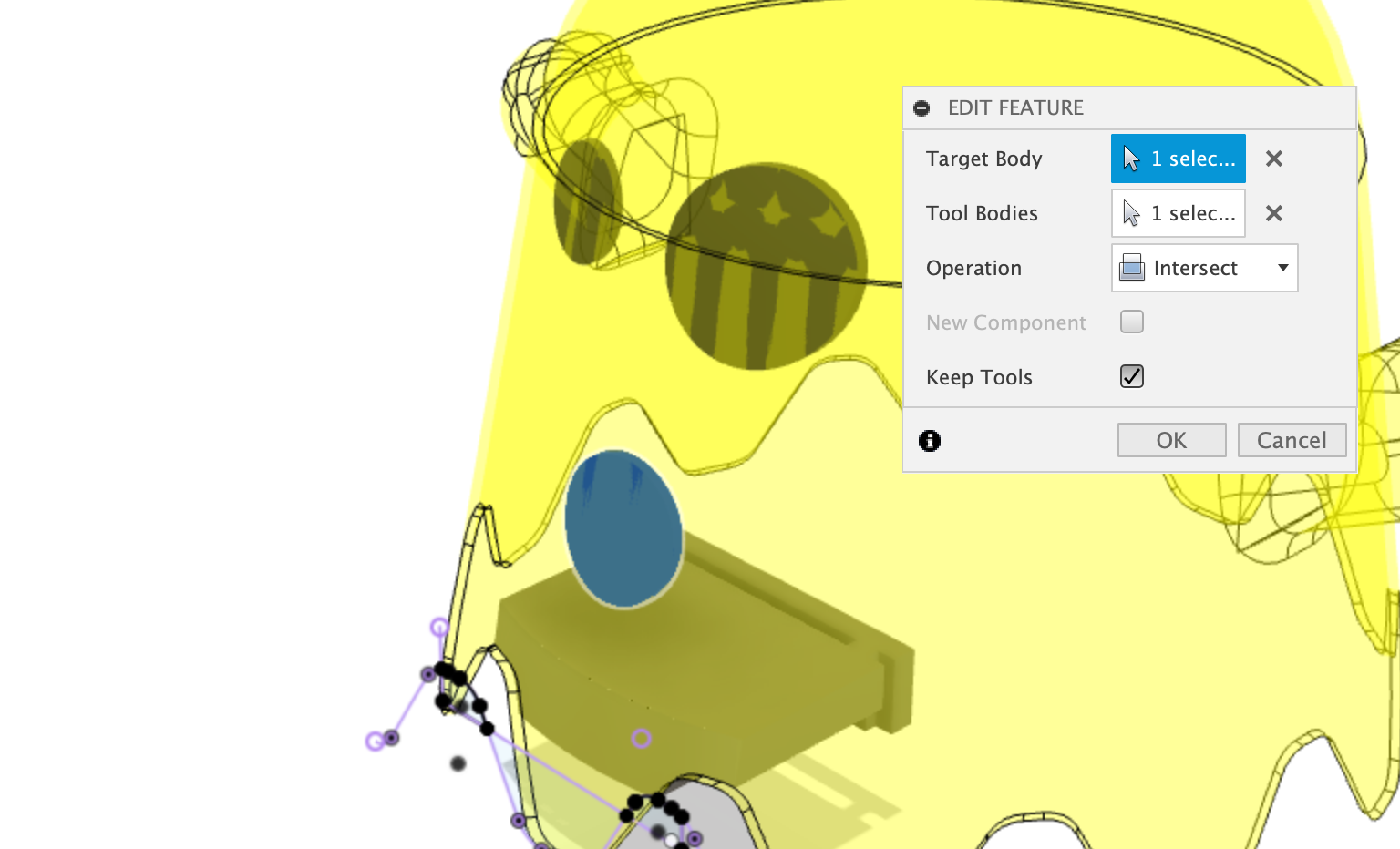
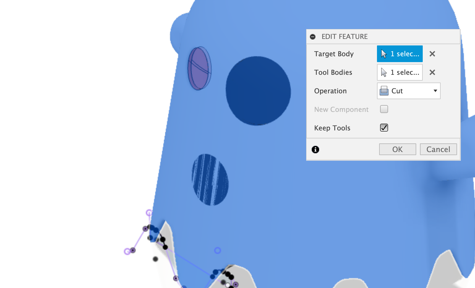
Combine (Intersect) the Eye with the body
Use the Combine command to intersect the eye body with the ghost body. Ensure the keep tools option is selected.
Do this for both eyes and the mouth:
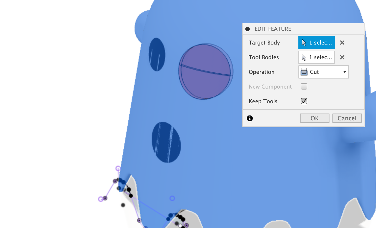
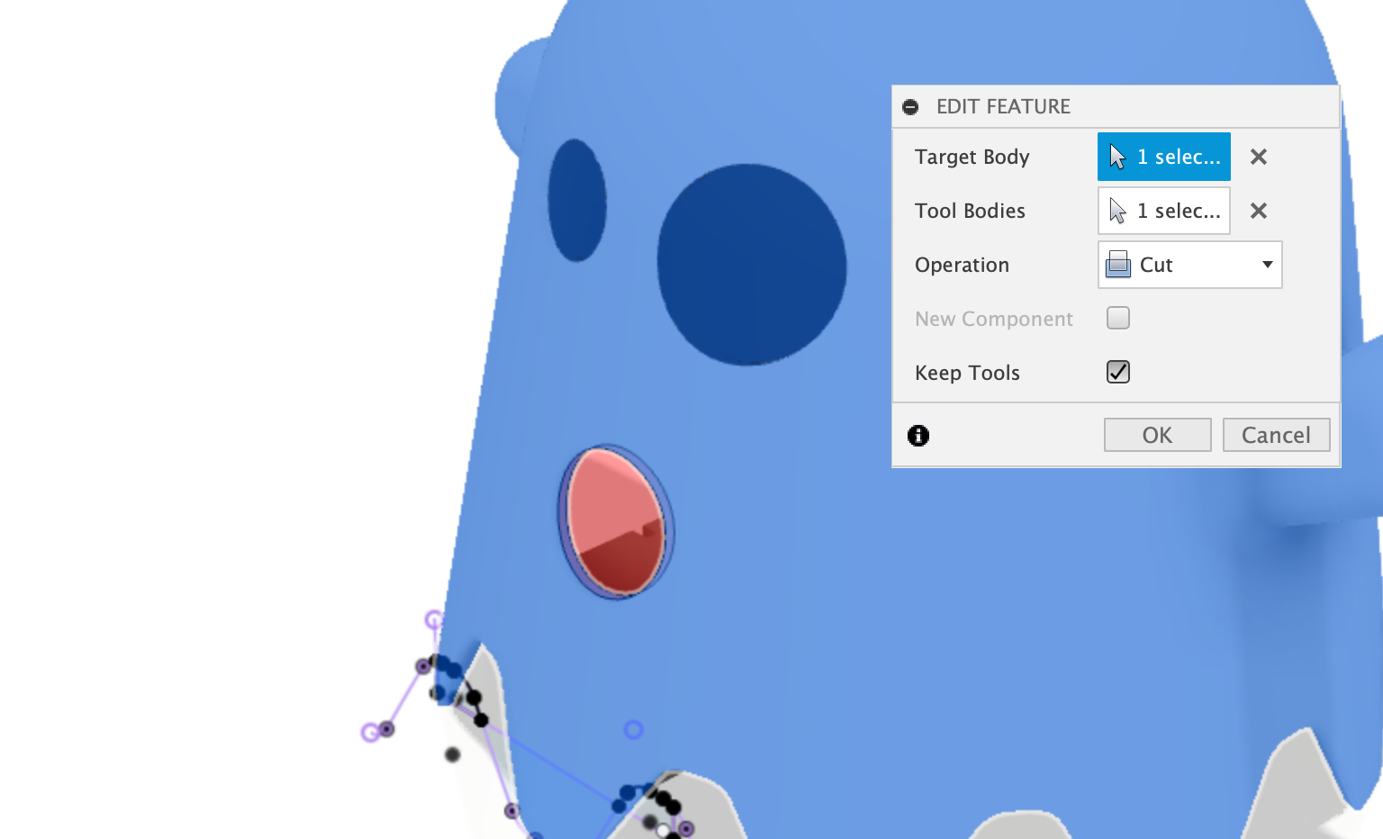
Combine (Cut) the Eye with the body
We will now use the same Comine command, but this time Cut the eyes and mouth from the body and keep the pieces (keep tools).
Cut the body up into segments for 3d Printing
Use the Split Body command to split the ghost body into segments. Select the Ghost body as the Body to Split, and select all four offset planes created earlier as the Spliting Tool(s).
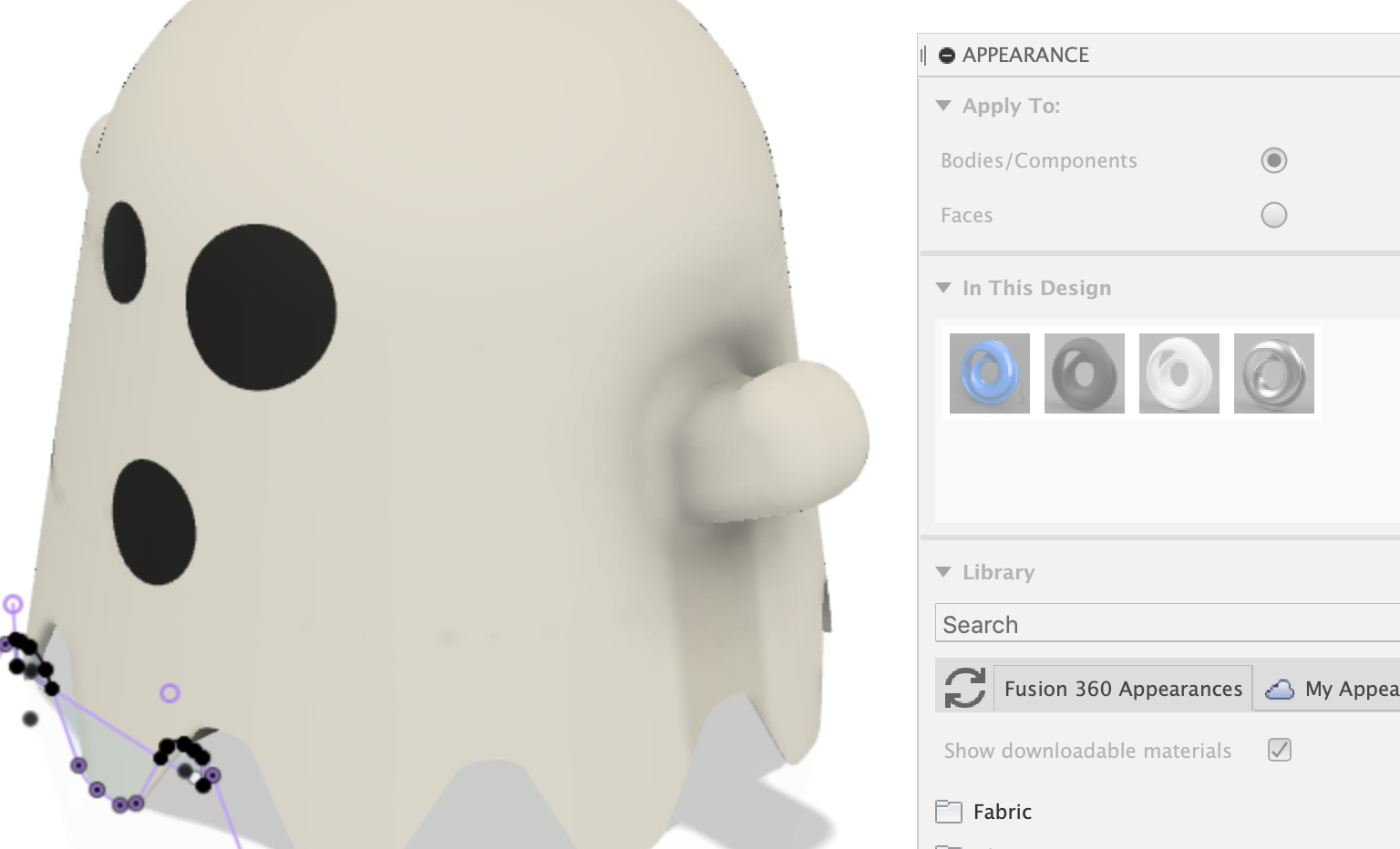
Appearance
Use the a Appearance command to change the colour of the parts - the mouth and eyes are Matte Black, and the body is Matte White.
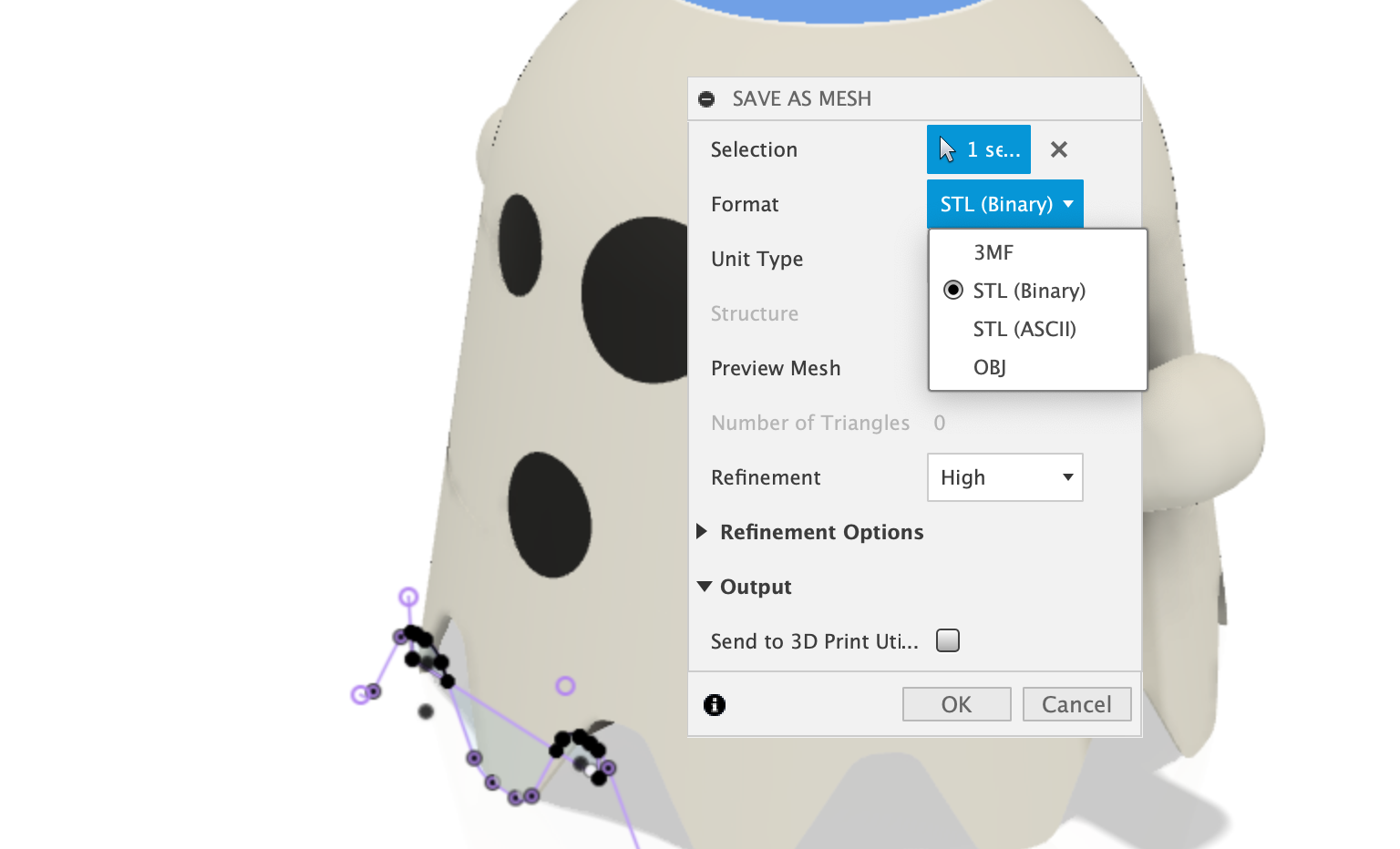
Export as Mesh (STL)
You can now save each body as an STL by right clicking each components Body and selecting Export to…
Do this for each of the components:
- Left Eye
- Right Eye
- Mouth
- All four Body Segments
You can now load these into your favourite STL slicer, such as Cura.
Videos
Watch the video(s) associated with this build:
Gallery