Build Instructions | Wiring the PCA9865 board to servos and Raspberry Pi Zero
Wiring Diagram
Wiring Diagram
Wiring the PCA9865 board to servos and Raspberry Pi Zero
Links
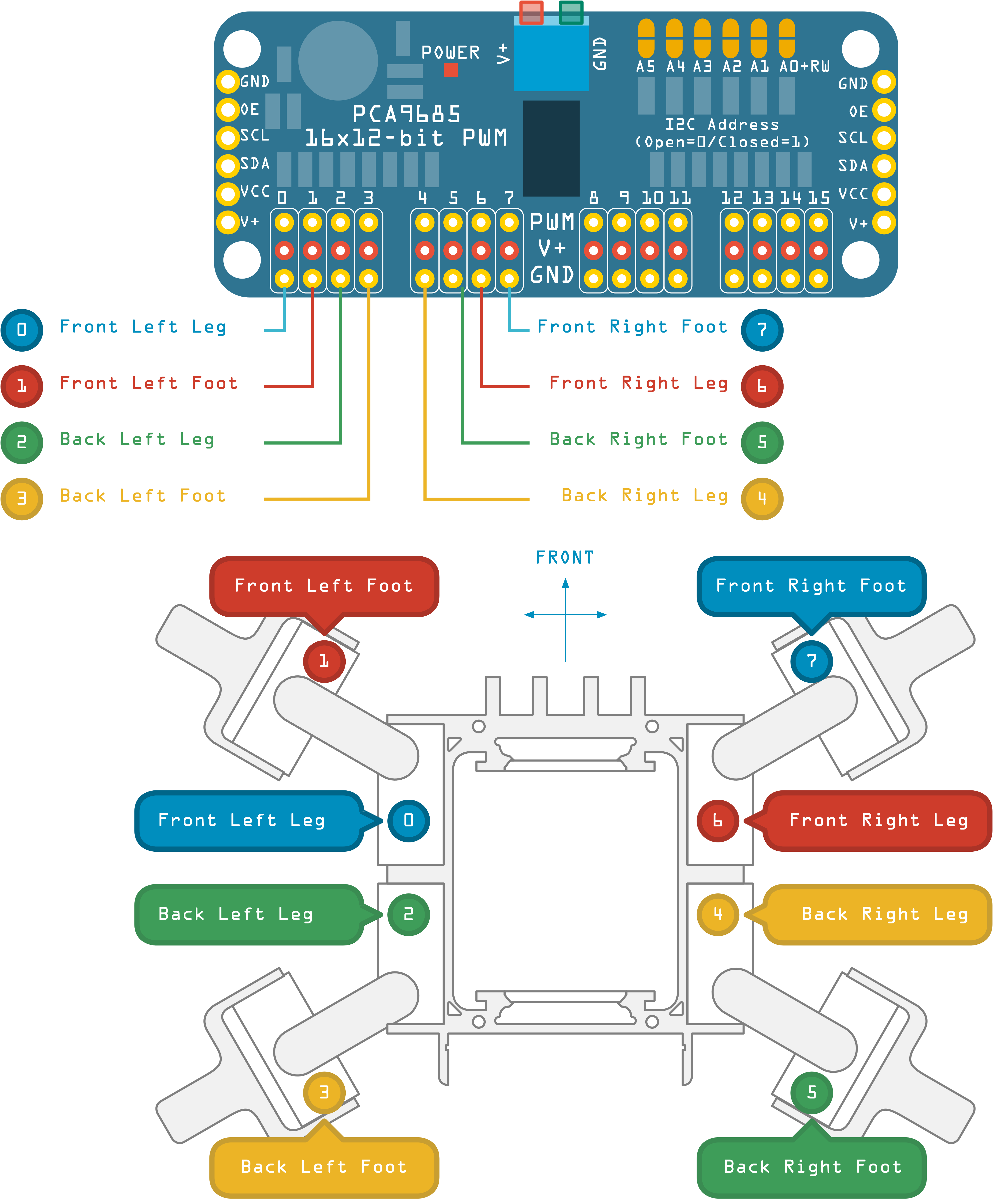
Wiring the Servos to the PCA9685 board
Connect the servos using the diagram below as a guide. The PCA9685 has 16 ports for connecting to servos, the Quad only uses 8 of these.
The table below shows the wiring for each limb, leg and foot:
| Servo # | Side | Front / Back | Type |
|---|---|---|---|
| 0 | Left | Front | Leg |
| 1 | Left | Front | Foot |
| 2 | Left | Back | Leg |
| 3 | Left | Back | Foot |
| 4 | Right | Back | Leg |
| 5 | Right | Back | Foot |
| 6 | Right | Front | Leg |
| 7 | Right | Front | Foot |
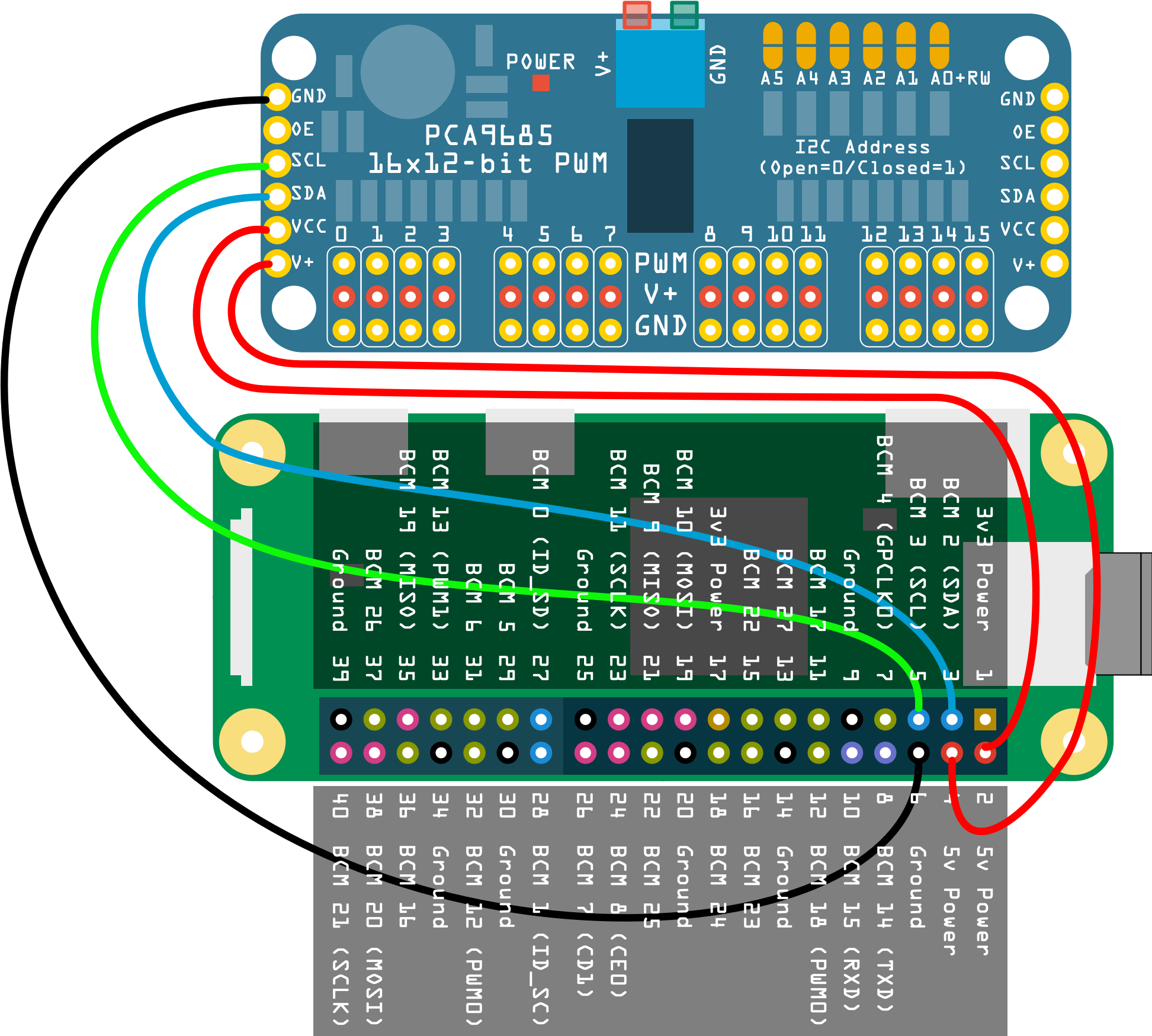
Wiring to PCA9685 to Raspberry Pi Zero
Next, the PCA9685 board needs to be wired to the Raspberry Pi Zero. There are 5 pins that we need to connect:
| PCA9685 Pin | Description | To Raspberry Pi Pin |
|---|---|---|
| GND | Ground | 6 |
| SCL | Sync Clock | 5 |
| SDA | Sync Data | 3 |
| VCC | 5v Voltage | 4 |
| V+ | 5v | 2 |
Please note the power supplied from the Raspberry Pi Zero to the Servos may not be suffient - you may need to attach a larger power supply (battery) to the Power + and GND at the top of the PCA9864 board.
SMARS Quad Build Instructions
Print Parts
Print the Servo Holders
Fit the servo into the servo holders
Fit the servo holders into the frame
Print the servo arms
Mount the servo holder into the servo arm
Check the servo rotation
Attach the other servo holders to the frame
Print the feet x4
Mount the foot on the servo holder
Check the servo rotation
Download the Python code
Wiring the quad