SMARS Chassis design
The Chassis design from start to finish
This detailed guide describes the all the steps required to create your own SMARS in a CAD package, so that you can go on to design and build more SMARS parts and customisations.
- Profiles
- The Chassis Base
- Extrude the Base
- Shell the Extruded Base
- Fillet the Shell
- Thin the Front and Back sides
- Front Cutout Profile
- Front Back Cut
- Side Profile
- Side Cutout
- Fillet applied to side cutouts
- Back cutout profile
- Back profile cut
- Chassis Wheel hole profile
- Wheel hole extrude cut
- Arduino slot profile
- Arduino slot cut
- Motor holder profile
- Motor holder profile extruded
- Motor nub profile
- Motor nub extrude
- Motor holder and nub chamfer
- Front profile
- Front cut
- Unpowered wheel stub profile
- Stub extrude profile
- Stub extrude
- Stub wheel profile
- Stub wheel revolve
- Stub wheel cutout profile
- Stub wheel cutout
- Motor holder slots profile
- Motor holder slot extrude-cut
- Final view
Profiles
The chassis is made of several sketch profiles:
- The base
- The side cutout
- The motor Holder
- The front cutout
- The back cutout
- The chassis Wheel hole profile
- The Arduino slot profile
- The motor holder profile
- The motor nub profile
- The front profile
- The unpowered wheel stub profile
- The stub extrude profile
- The stub wheel profile
- The stub wheel cutout profile
- The Motor holder slots profile
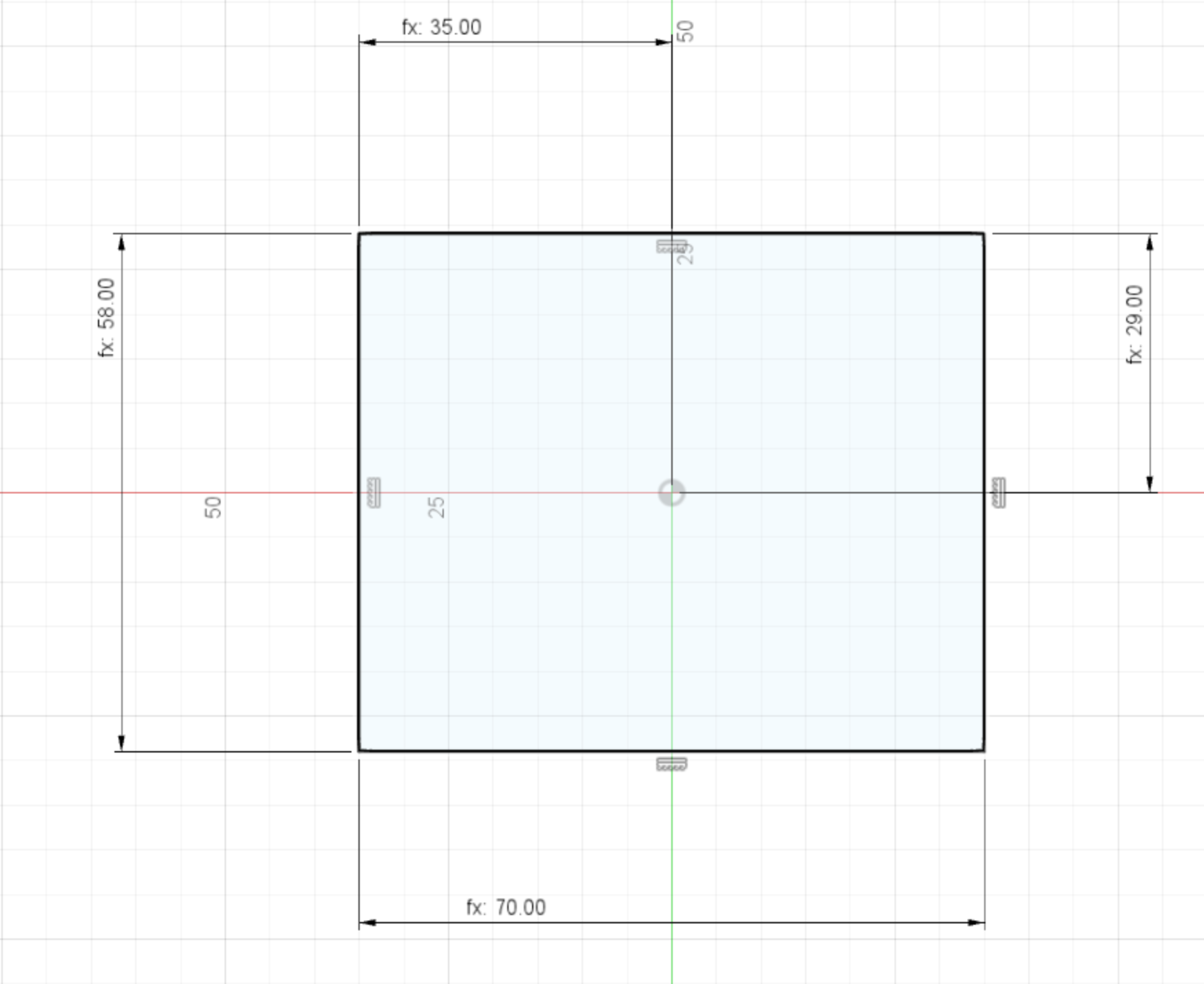
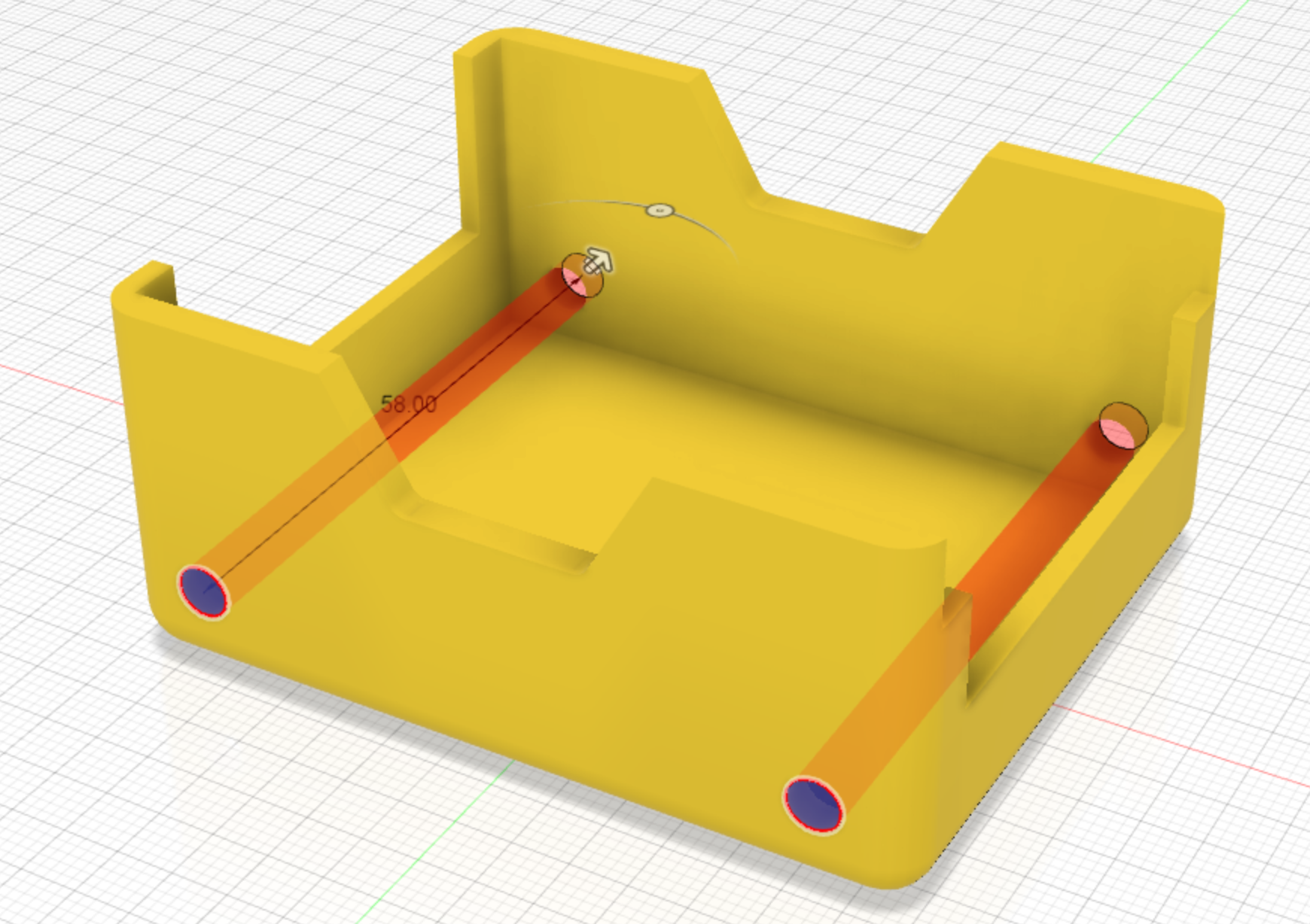
The Chassis Base
The Chassis Base is made of up 2 dimensions:
- Length = 70mm
- Width = 58mm
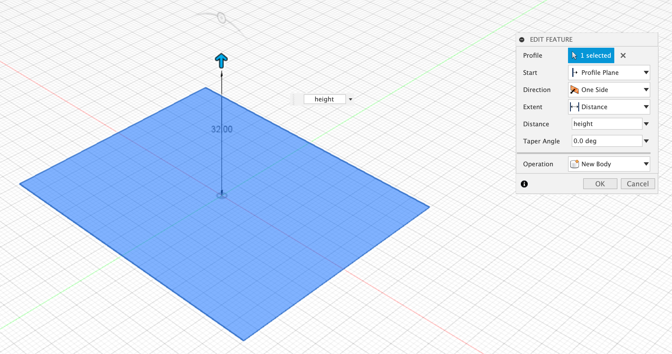
Extrude the Base
2 The base is then extruded up:
- Height = 32mm
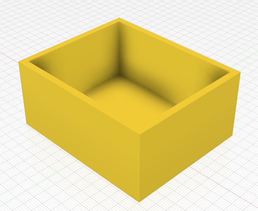
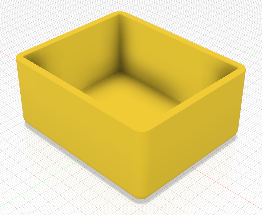
Shell the Extruded Base
Next a shell is applied to the extruded base cube, making it more into the familar shape, if not a little blocky.
- Shell thickness = 3mm
Fillet the Shell
The Chassis is now given a fillet around the bottom edges and each of the corners, to make it pleasing to the eye.
- Roundness = 4mm
Thin the Front and Back sides
The Front and Back sides are currently the case thickness from the shell we applied earlier. This needs to be trimmed down so that they are only 2mm thick.
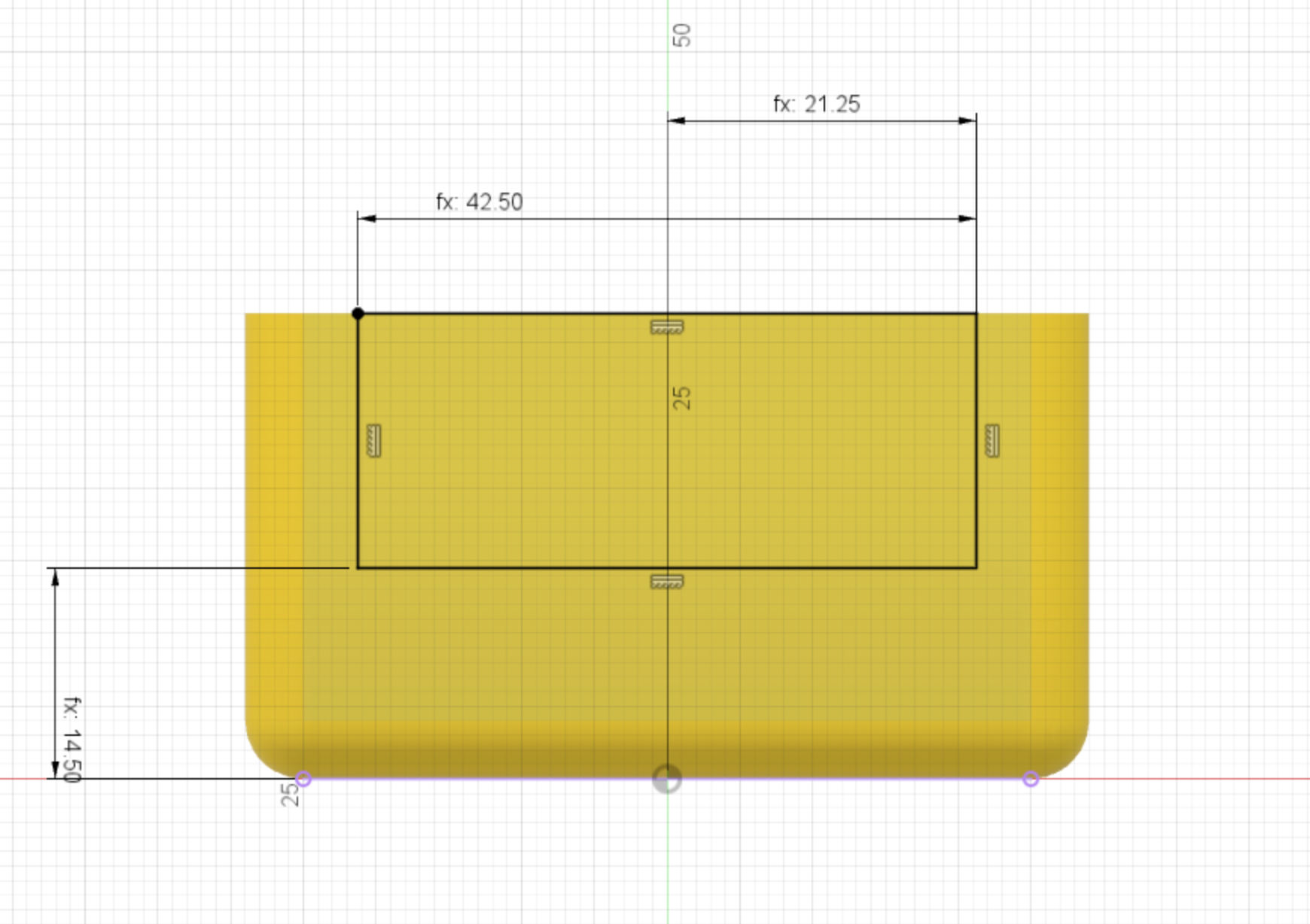
Front Cutout Profile
The Front and Back sides need to have a section cut out of them, first we need to create a profile for the cutout.
There are 2 main dimensions.
- Width = 42.5mm
- Height from bottom edge to the base = 14.5mm
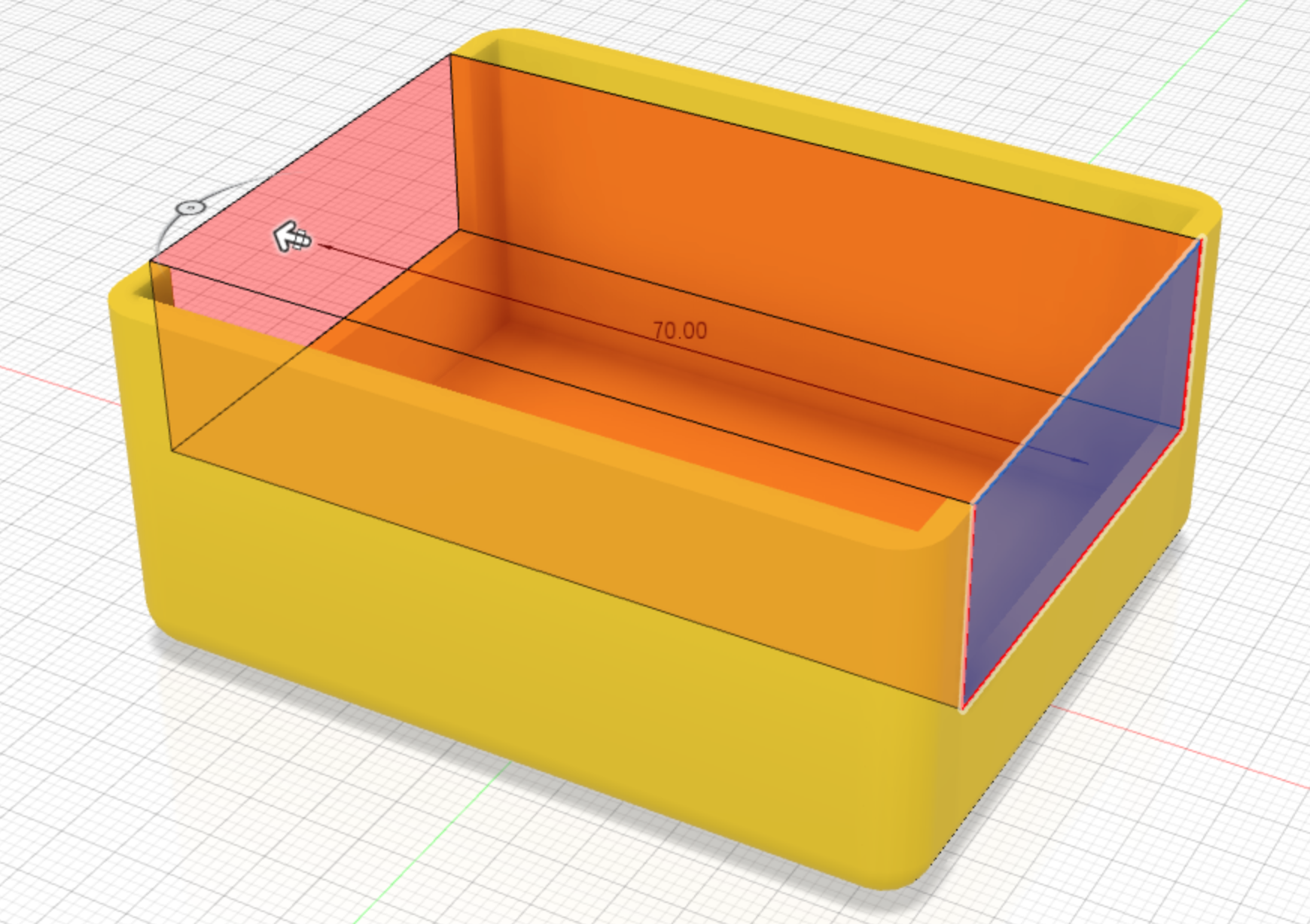
Front Back Cut
The profile created previously is now used to extrude a cut all the way through the body.
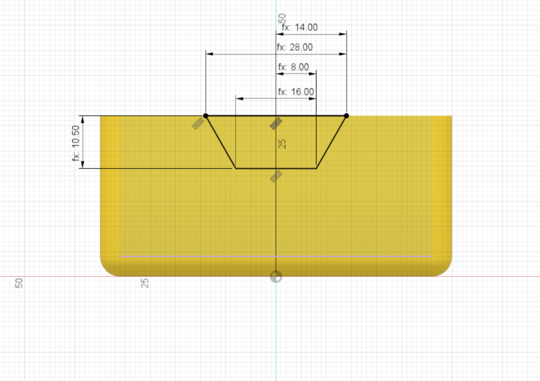
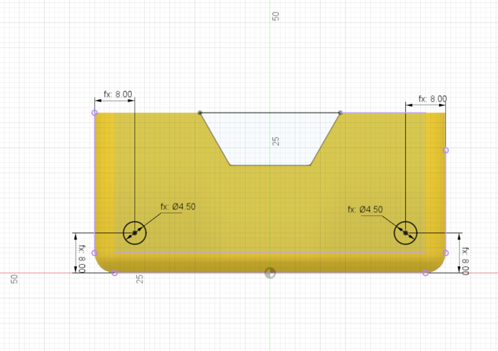
Side Profile
The profile for the side cutout is created next. This is a inverted trapesium shape, with three main dimensions:
- Top width = 28mm
- Bottom width = 16mm
- Depth = 10.5mm
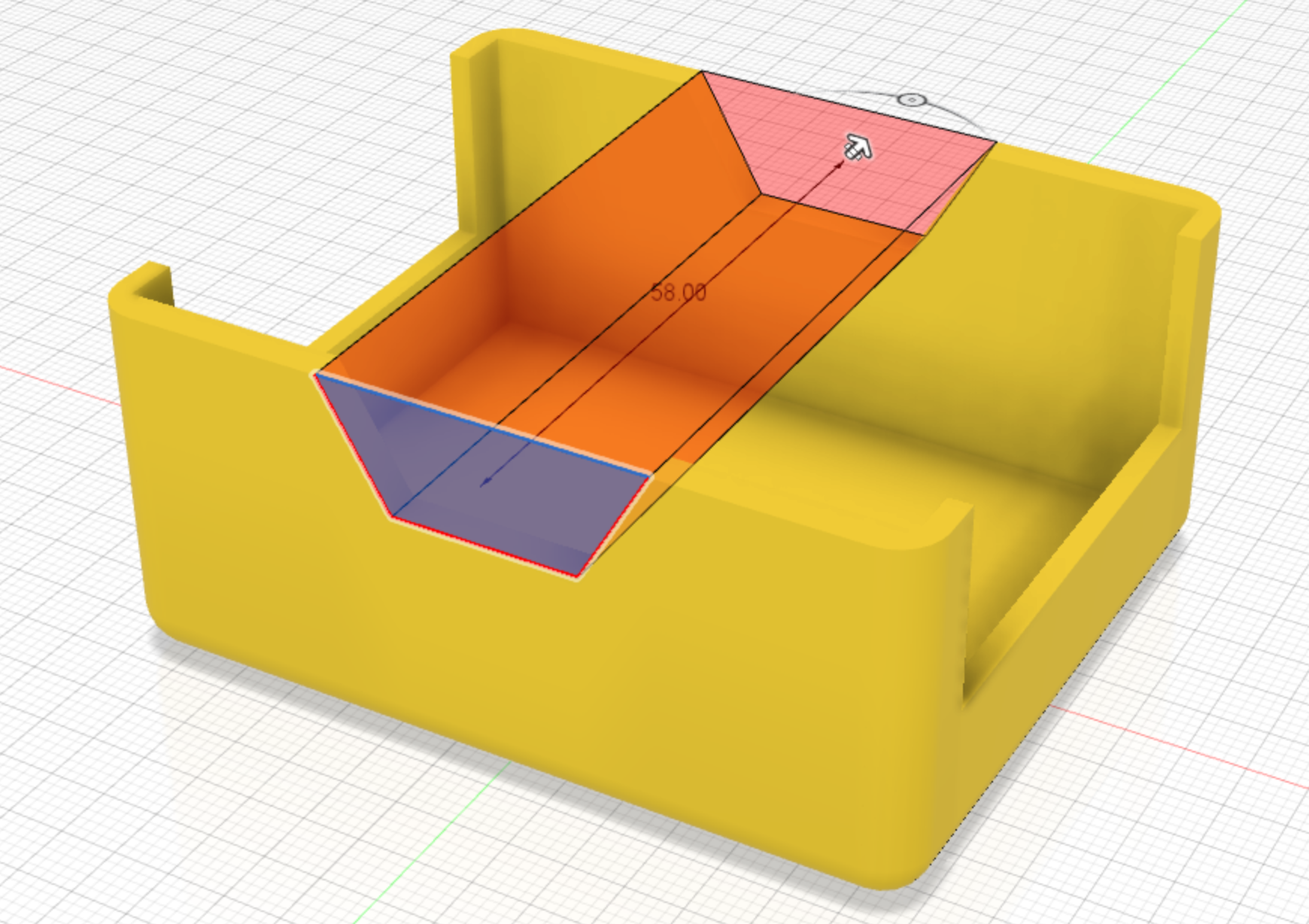
Side Cutout
The side profile is now extruded to cut all the way through the main body.
Fillet applied to side cutouts
A small fillet of 1.5mm is applied to round the inner edges of the cutout that has just been applied.

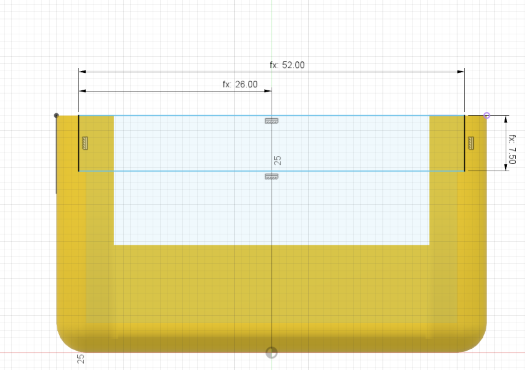
Back cutout profile
A profile is created for the back cutout section. This has 2 dimensions:
- width = 52mm
- depth = 7.5mm
Back profile cut
The profile created above is used to extrude a cut through the back side of the body. This is where the arduino will slide in. The slots will come shortly.
Chassis Wheel hole profile
The profile for the wheel holes is created next. This has 2 dimensions:
- Hole diameter = 4.5mm (the motor spindle is 3mm so this is plenty of clearance)
- Hole centre from edge and bottom = 8mm
Wheel hole extrude cut
The wheel hole profile is used to extrude a cut all the way through the body.
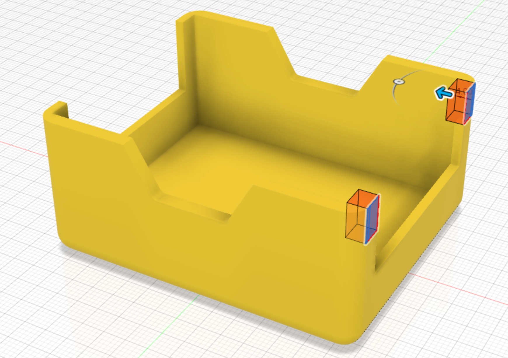
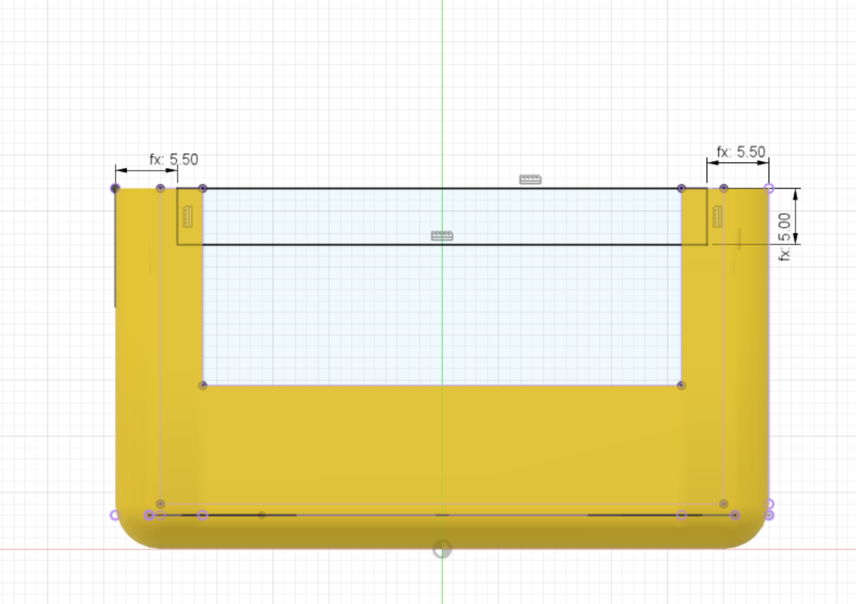
Arduino slot profile
The slots for the arduino are sketched next. They go all the way from the back edge to the inner front edge. The dimensions of the Arduino slots are:
- Slot height = 2mm
- Body top to slot bottom edge = 5.5mm
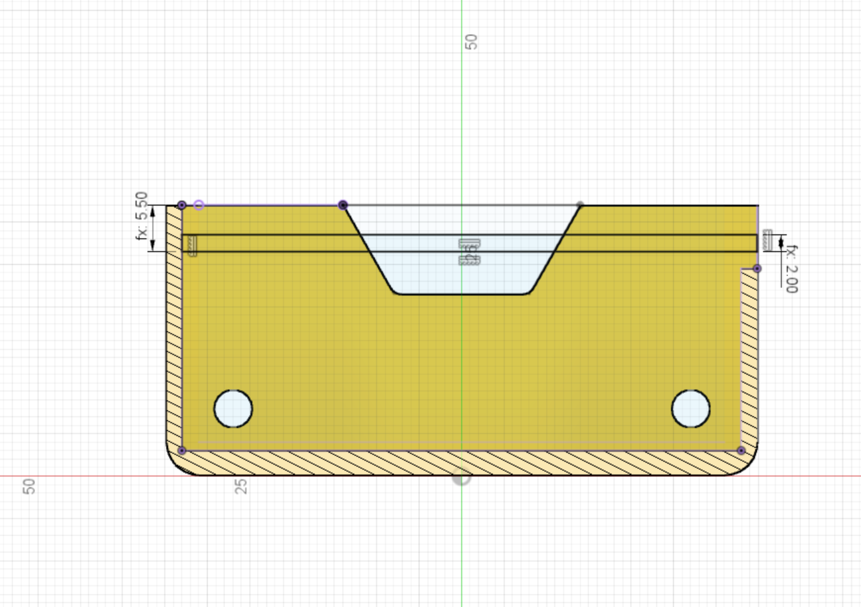
Arduino slot cut
The Arduino slot profile created above is used to extrude a cut into the body, to a depth of 0.5mm.
- Arduino slot depth 0.5mm
This feature is mirrored across to the other side of the chassis.
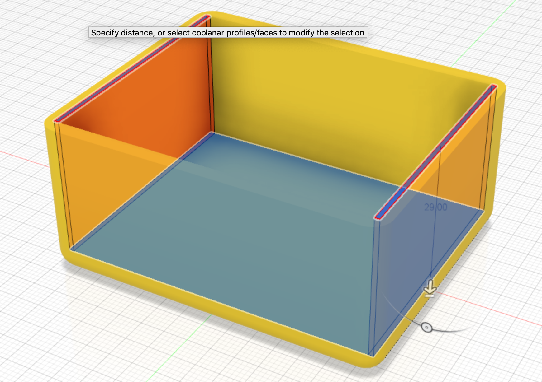
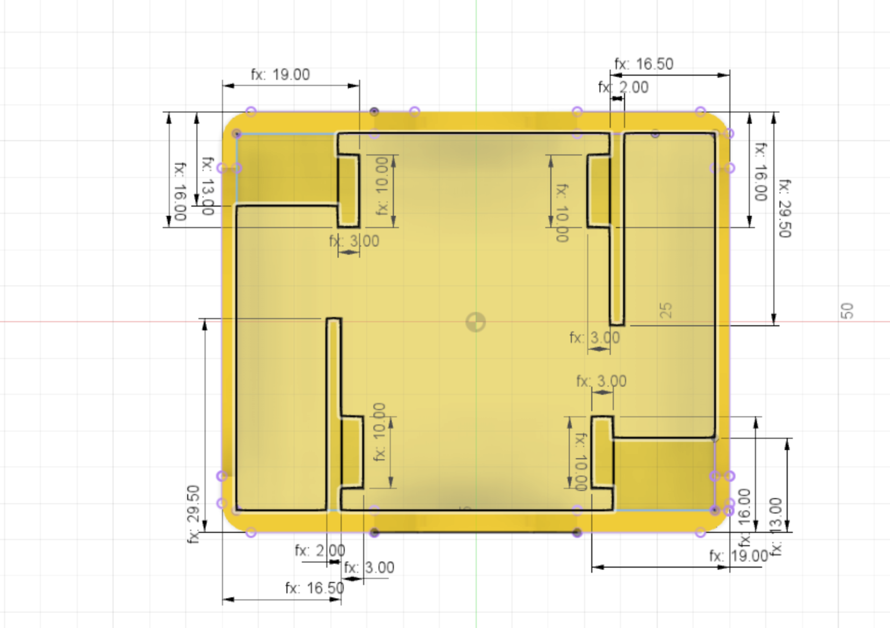
Motor holder profile
The profile for the motor holders within the body is created next. There are a couple of dimensions on this sketch:
- motor holder side wall thickness = 2mm
- motor holder side wall edge from body edge = 16.5mm
- motor holder wall height = 29.50mm
- unpowered wheel block from case edge = 13mm
- unpowered wheel block and battery nub from edge = 19mm
- battery nub height = 10mm
- battery nub thickness = 3mm
The top half of the sketch can be created and then a circular pattern used to rotate this around the centre to create an asymetric mirror for the bottom half of the sketch.
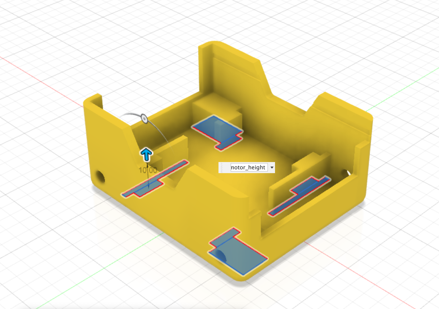
Motor holder profile extruded
The Motor holder profile is used to extrude up the motor holders. The dimesions are:
- height = 10mm
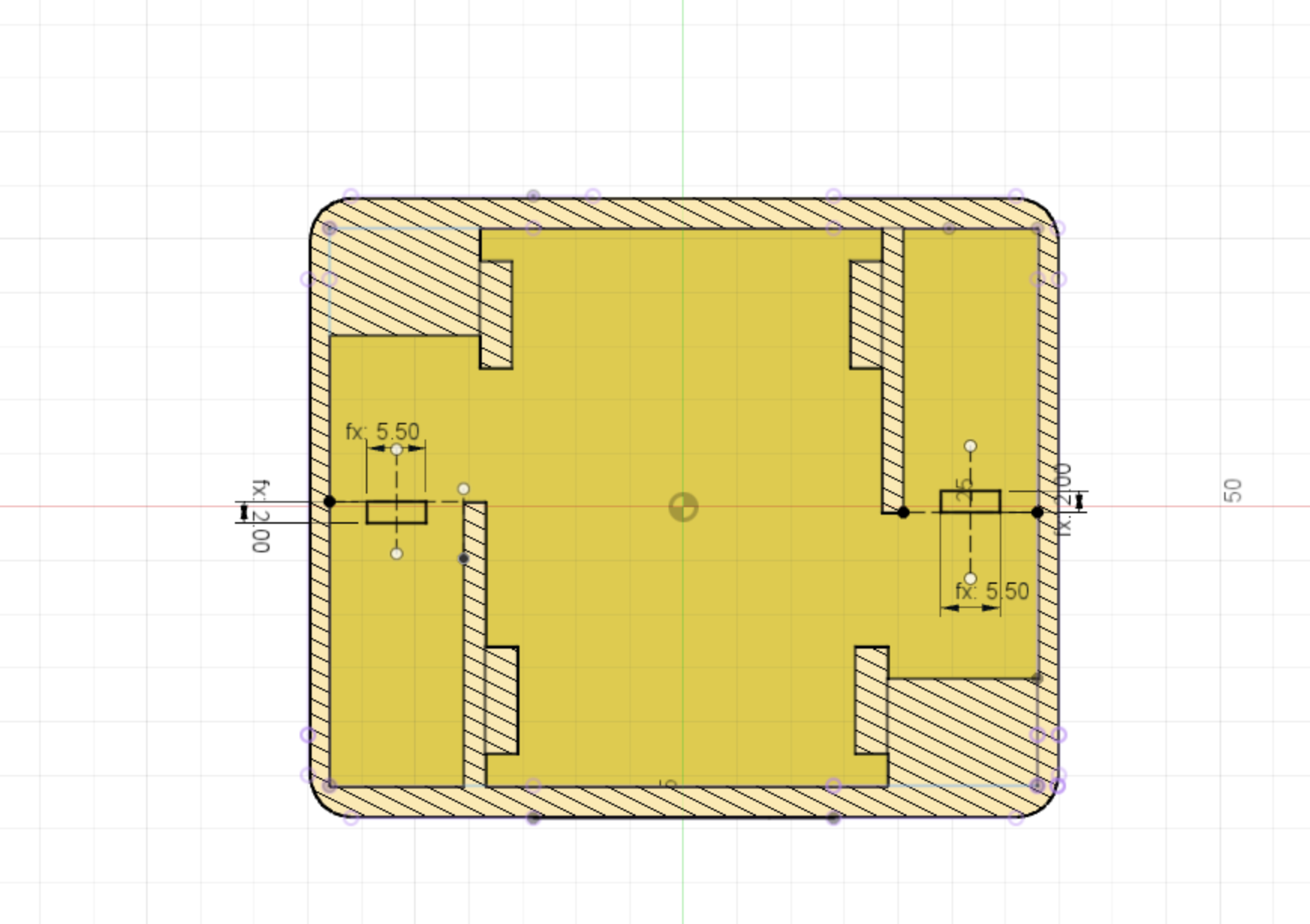
Motor nub profile
A small nub needs to be sketched - this is to prevent the motor from sliding backwards into the chassis body.
The dimensions are:
- motor nub height = 2mm
- motor nub width = 5.5mm
They are aligned to the top of the motor holder sides and centered with in that area.
Motor nub extrude
Using the Motor nub profile created earlier, we extrude the Motor nub up by:
- Motor nub extrude height = 2mm
Motor holder and nub chamfer
A small chamfer is applied to the tops of the extruded motor holder profiles and motor nubs.
The dimension of the chamfer is:
- motor holder chamfer = 1mm
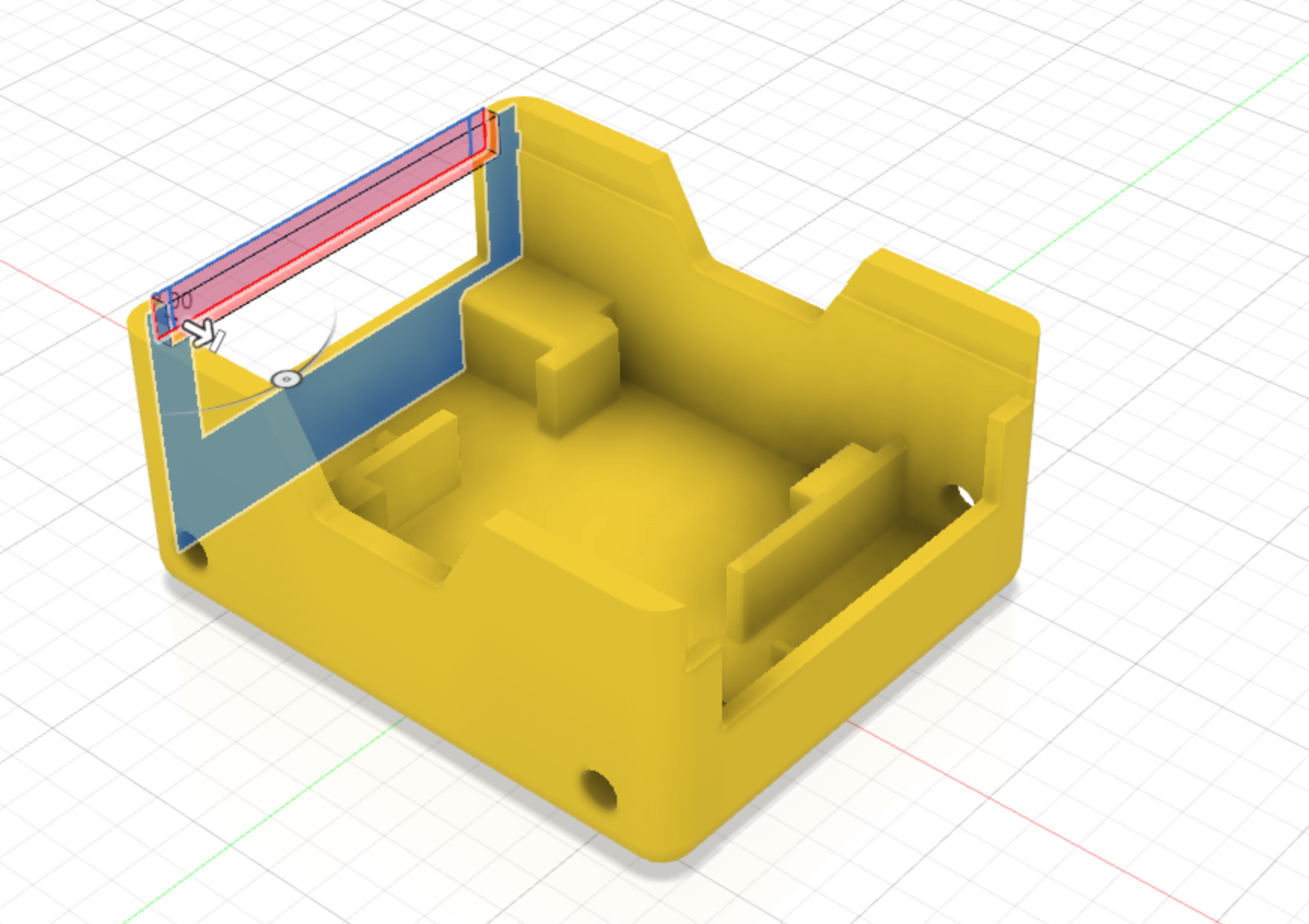
Front profile
A profile sketch is needed to make a final cut to the front side.
The dimensions of the cut are:
- width = 5mm
- distance from chassis side to profile = 5.5mm
Front cut
The Front profile created above is used to extrude a cut into the front side of the chassis.
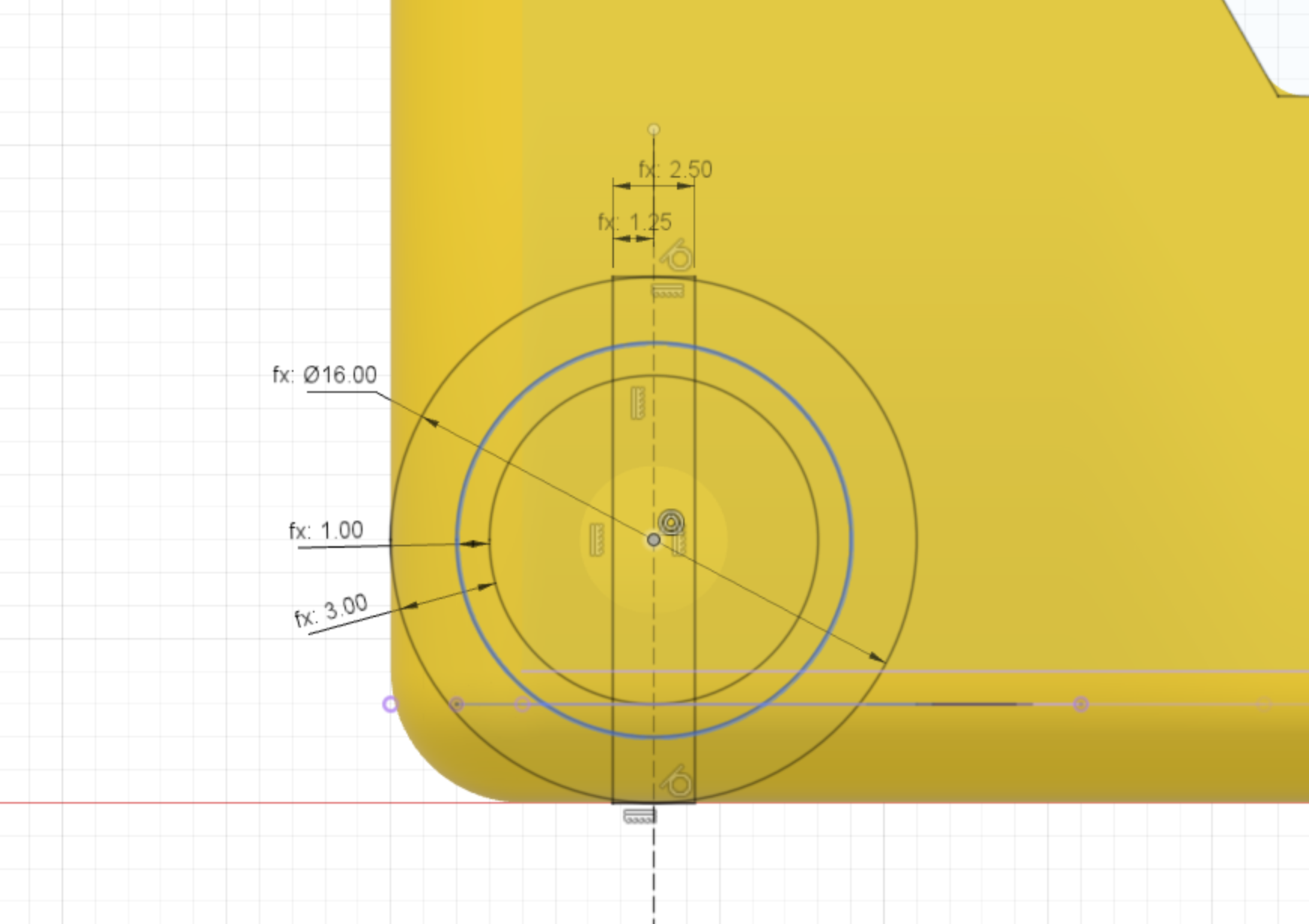
Unpowered wheel stub profile
The unpowered wheel stub profile is sketched next.
This has several dimensions:
- stub diameter = 16mm
- stub inner diameter = 3mm (offset from stub diameter)
- stub flat diameter = 1mm (offset from the stub inner diameter)
- stub cut out slot width = 2.5mm
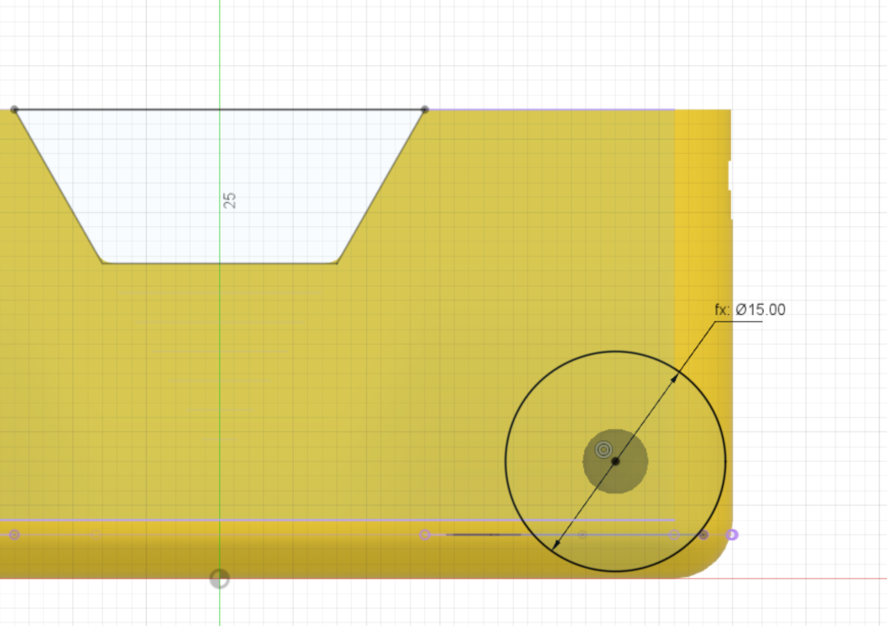
Stub extrude profile
A small extrusion is needed to join the stub wheel to the fillet at the bottom of the chassis.
Dimension:
- stub wheel diameter = 15mm
The center of the circle is located at the centre of the previously extruded motor hole.
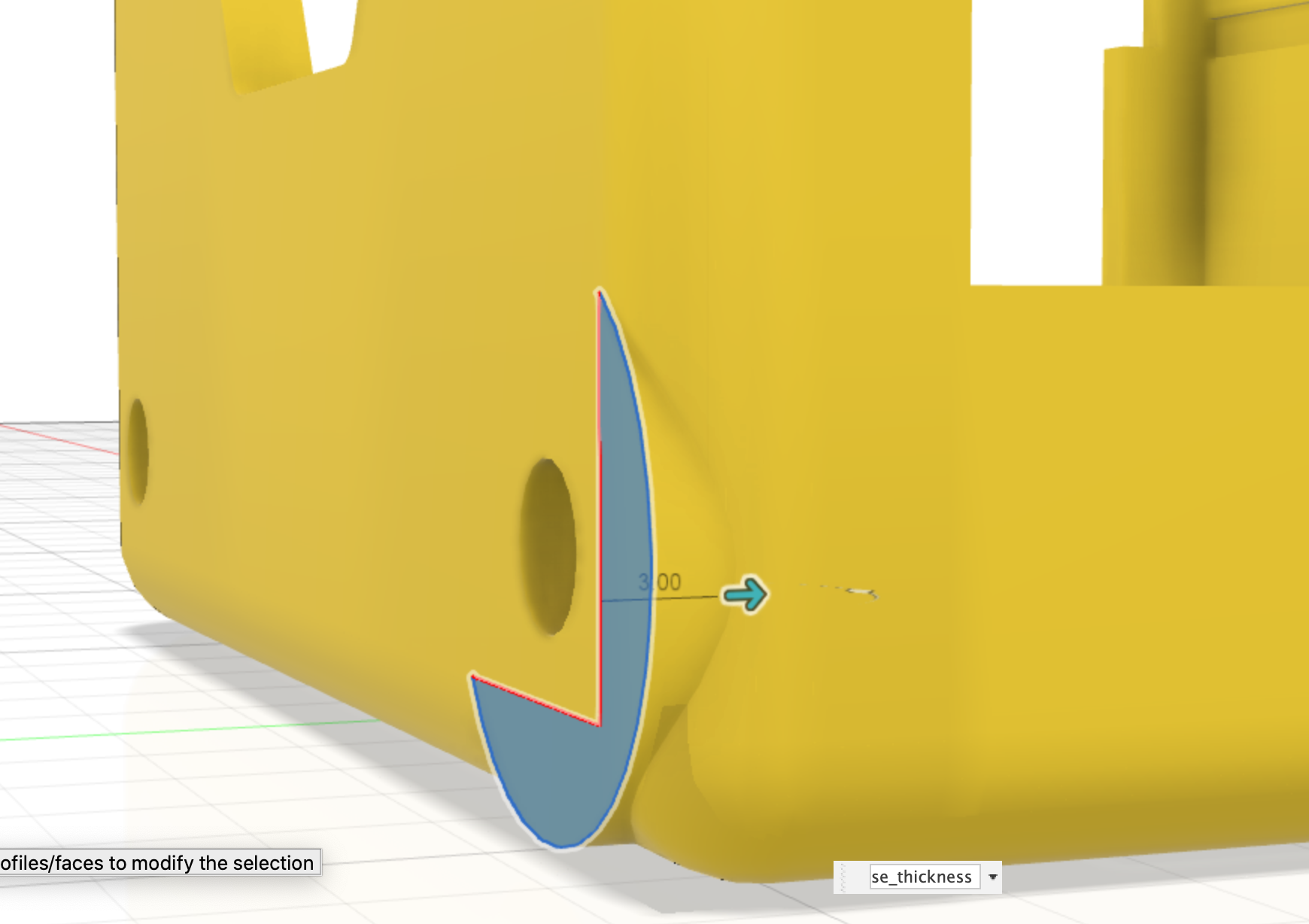
Stub extrude
The Stub extrude profile is extruded into the chassis body. The dimensions are:
- stub extrude 3mm
This feature is replicated to the other side of the case using a circular pattern.
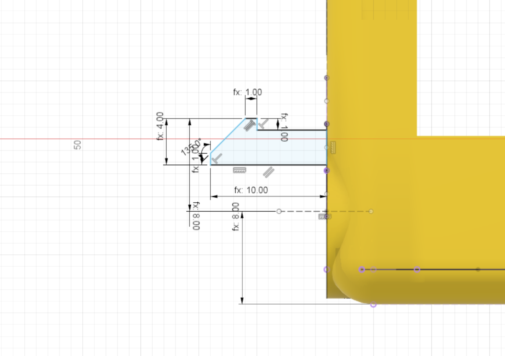
Stub wheel profile
The stub wheel is actually created using a profile that is then revolved around an axis to form a rounded part.
This is a complex part to describe so please refer to the diagram below for dimensions.
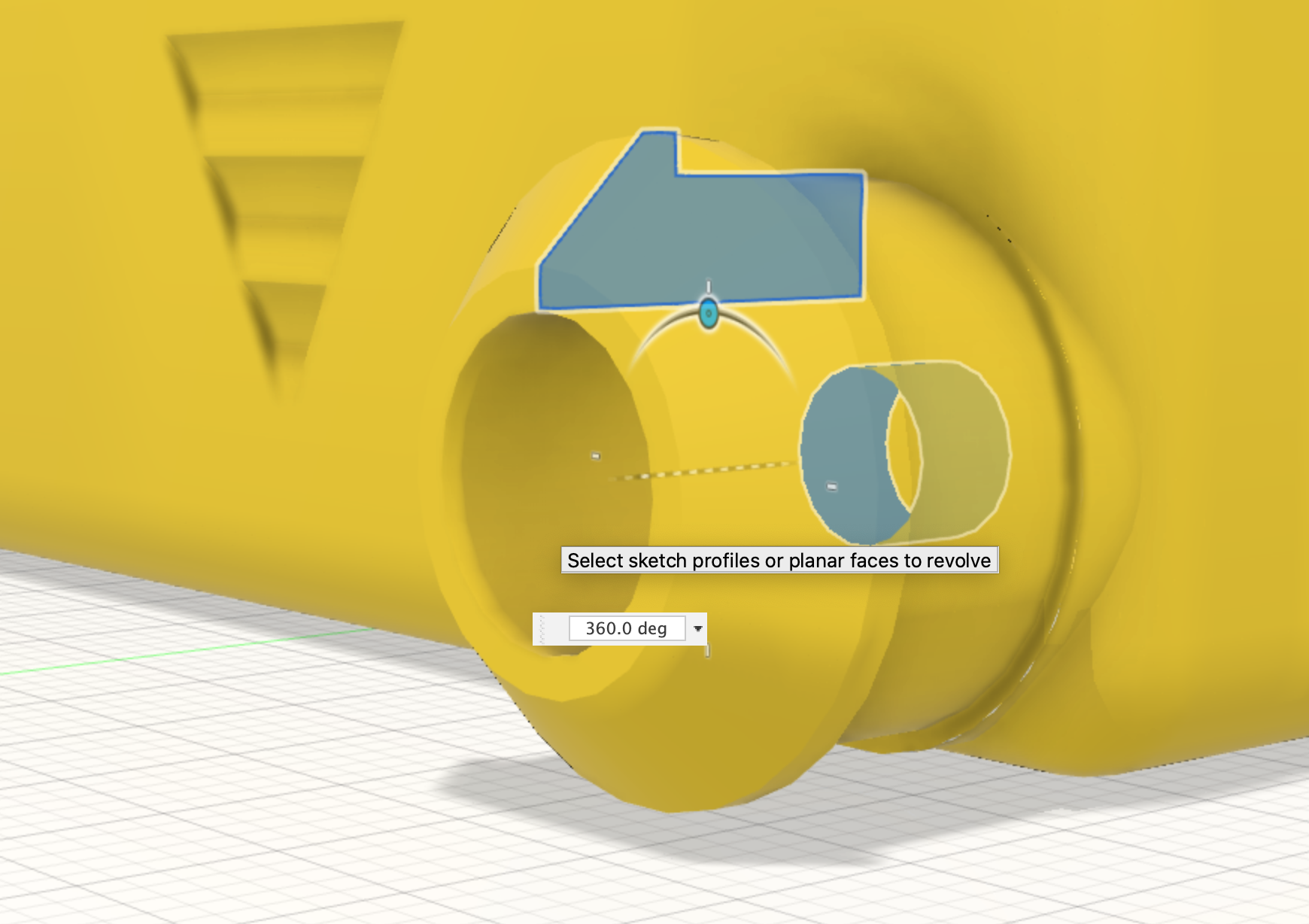
Stub wheel revolve
The Stub wheel profile created above is revolved around the center of the wheel hole to create a solid body. The revolve operation also joins this to the chassis.
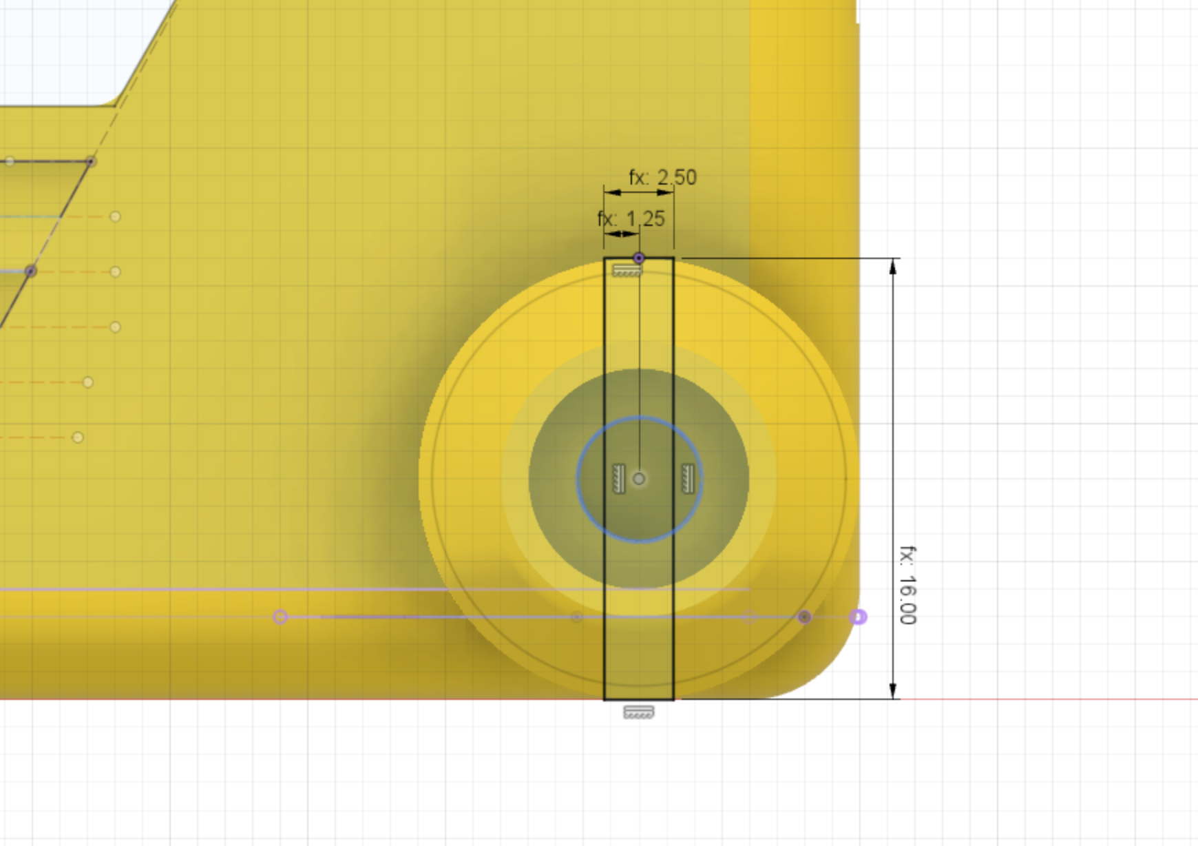
Stub wheel cutout profile
The stub wheel needs a cut out section to allow the two halfs of the stub wheel to squeeze together when pushing on an unpowered wheel.
The dimensions are:
- cutout width = 2.5mm
- cutout height = 16mm (the wheel diameter)
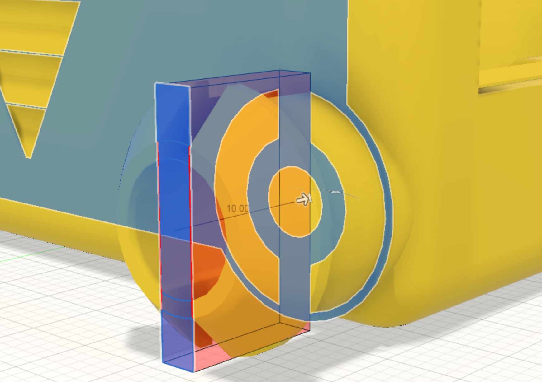
Stub wheel cutout
The Stub wheel cutout profile is used to extrude-cut the section into the stub wheel to create two halfs.
The cut operation goes through the stub wheel to the surface of the side of the chassis body.
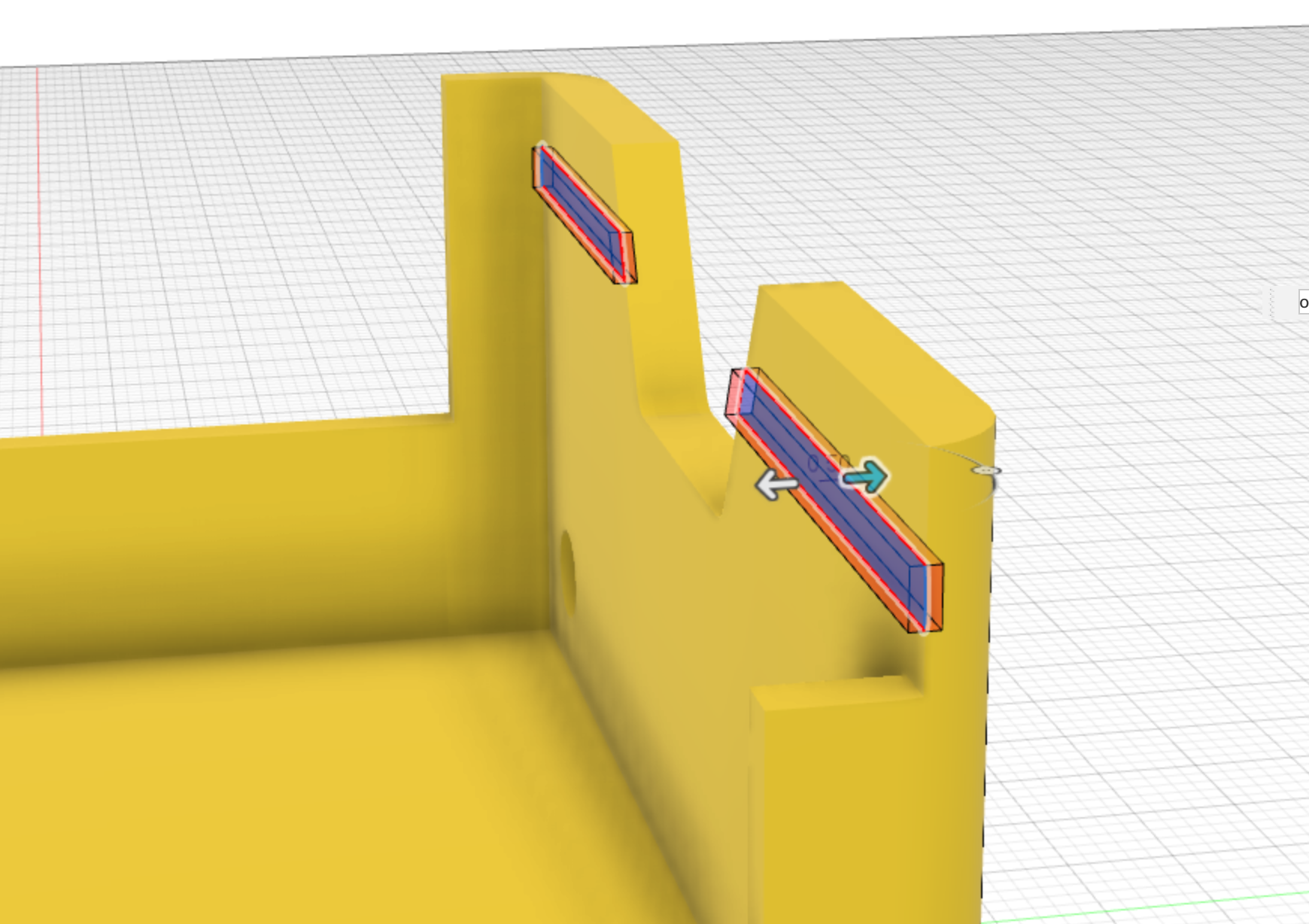
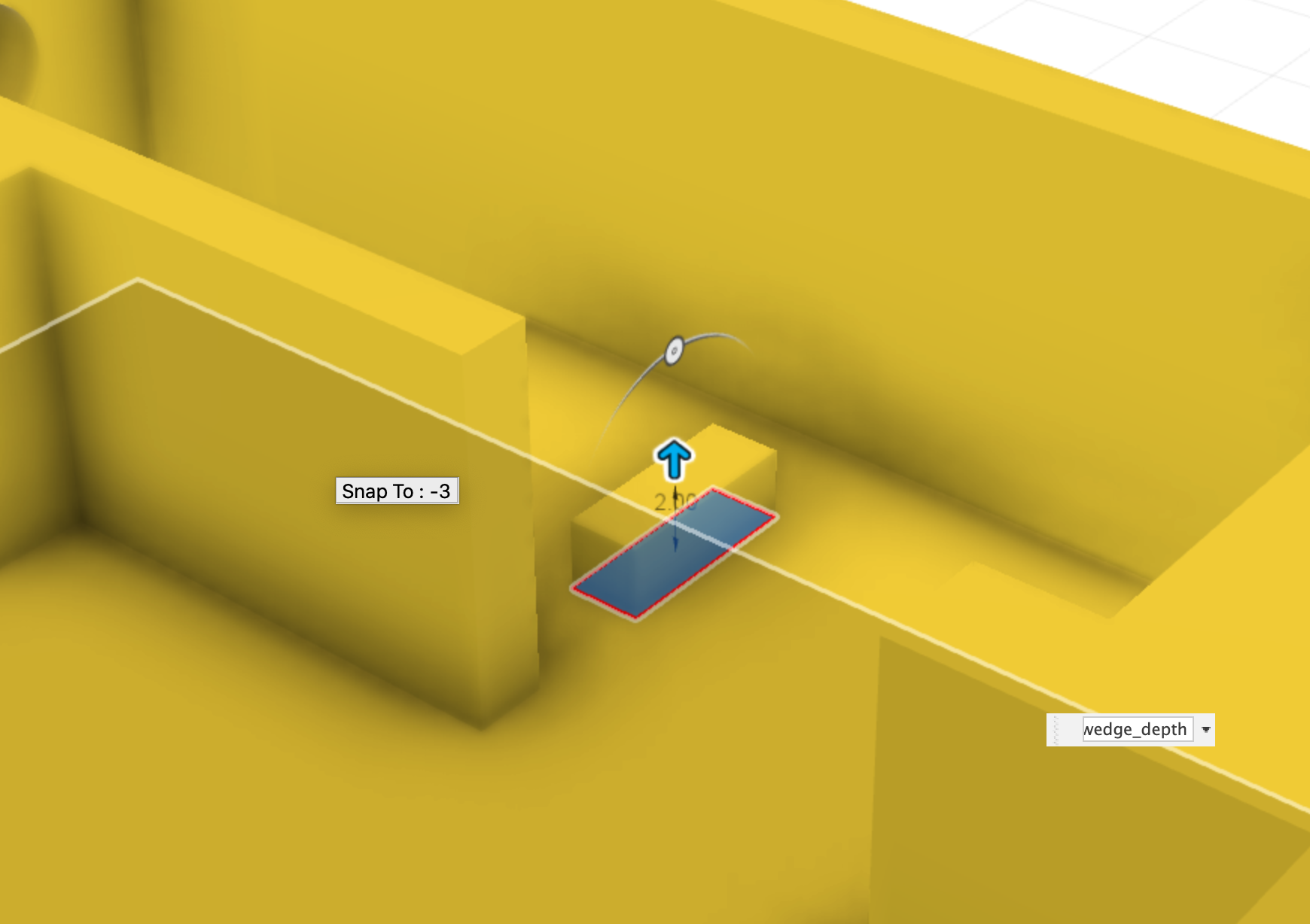
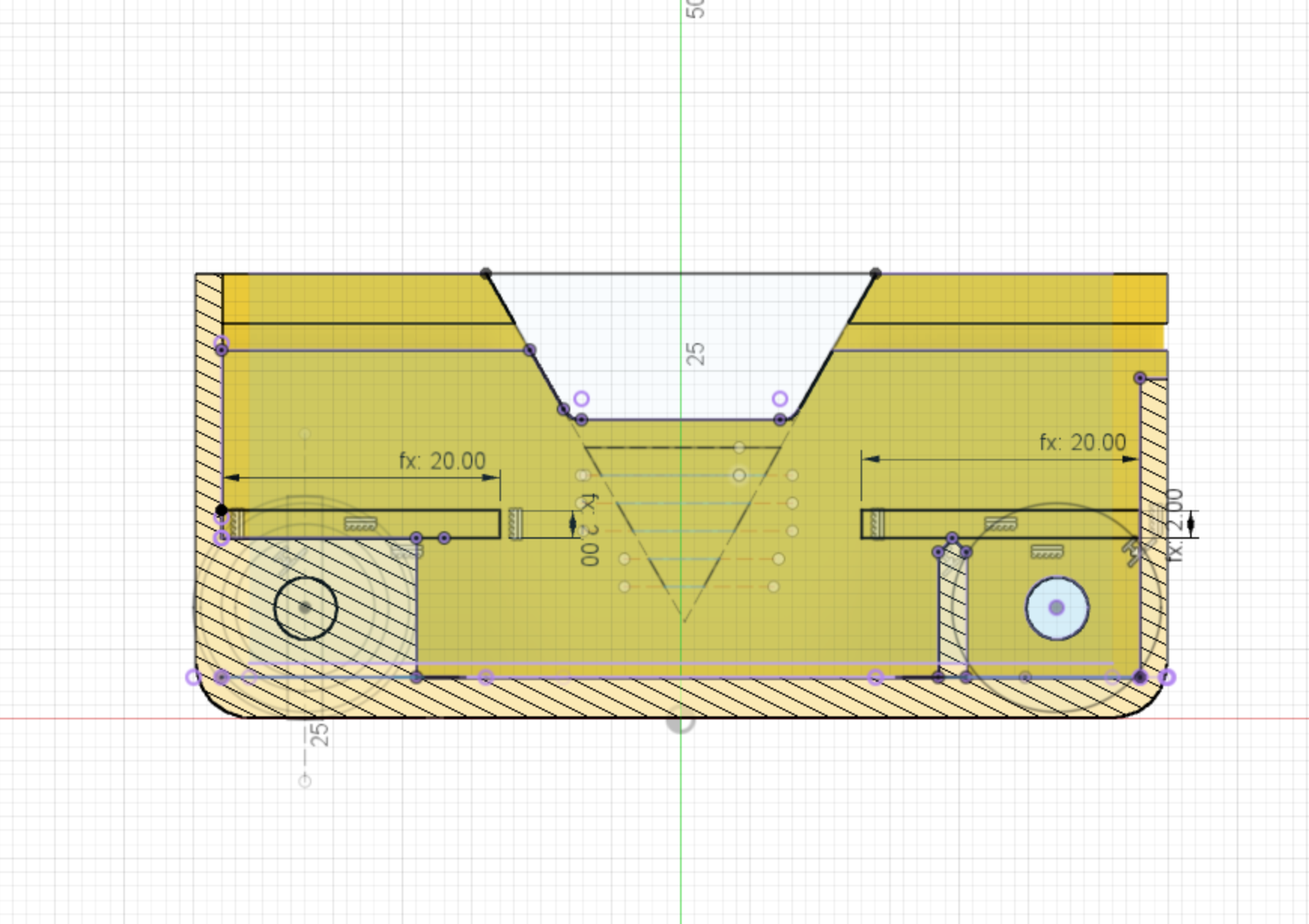
Motor holder slots profile
Two slot profiles need to be sketched above each of the areas where the motors live. This will enable a motor holder part to be snaped into place later once the motors are installed. The parts are pressure fit, so this part will only need to be a few mm deep.
Dimensions:
- length = 20mm
- depth = 2mm
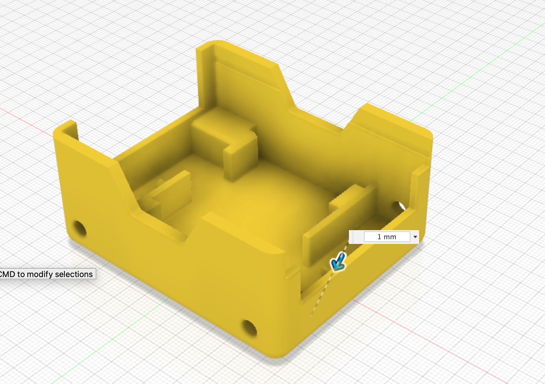
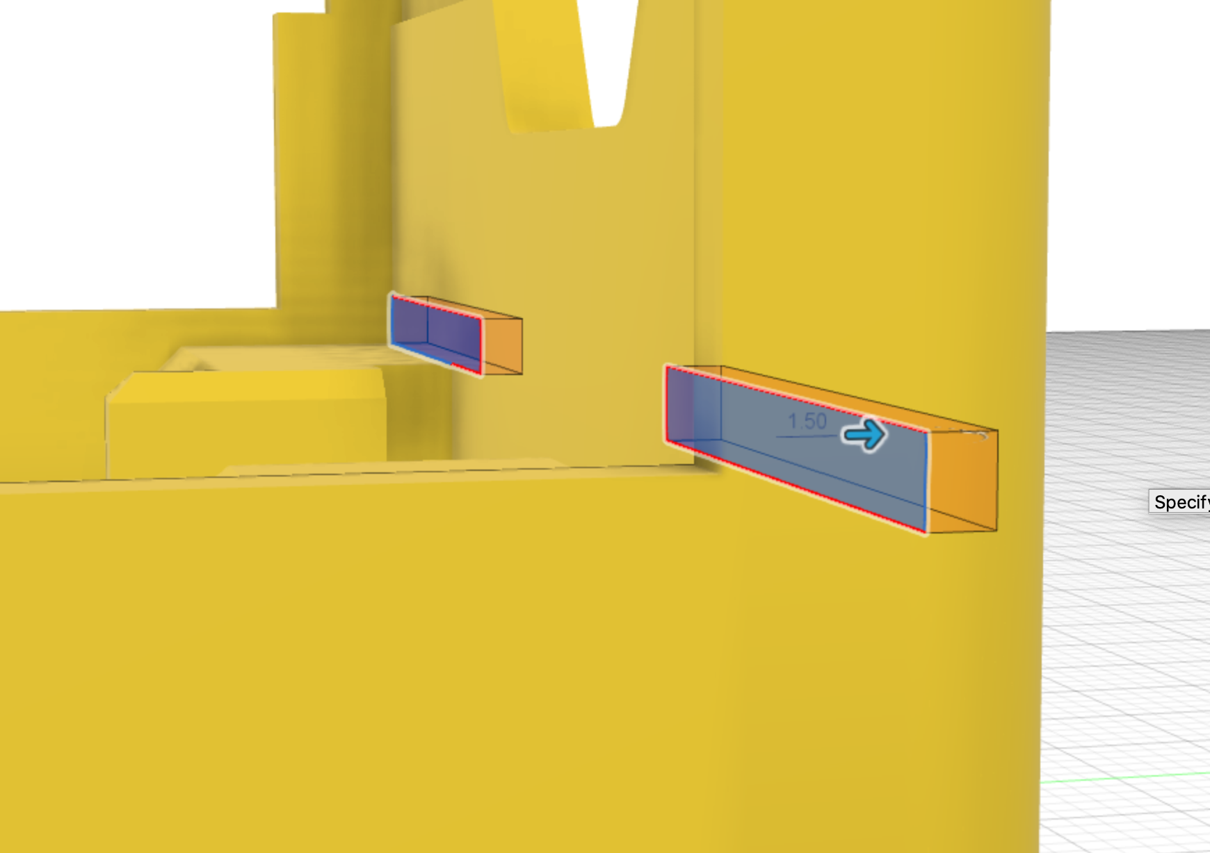
Motor holder slot extrude-cut
The Motor holder slots profile is used to extMotrude-cut the slots into the chassis.
The dimensions for the cut are:
- extrude cut depth = 1.5mm
This feature is then mirrored across to the other side of the chassis.
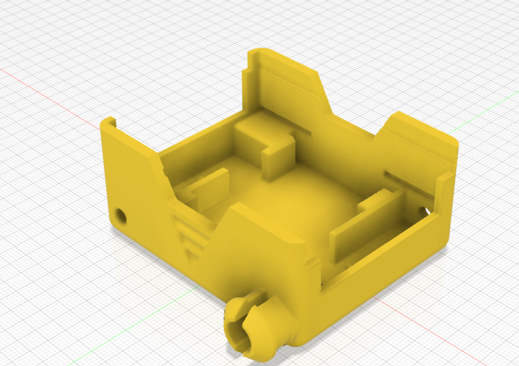
Final view
You should now have a finished Chassis design, ready for saving out to an STL file and printing.
(Note this design has a few extra florishes)