Wheel Design
SMARS Wheel design
This detailed guide describes the all the steps required to create your own SMARS Wheels in a CAD package, so that you can go on to design and build more SMARS wheel designs and customisations.
First the Unpowered wheel will be created, then the Master wheel will be derived from this, finally the inner wheel will be derived from the unpowered wheel.
- Dimensions Table
- Base Sketch
- Extrude Base Sketch
- Create Octogon
- Extrude-Cut Octogon
- Create Sketch - Stub cutout
- Extrude-Cut the Stub Wheel
- Extrude Join Rim
- Fillet Rim
- Create Midplane
- Mirror Rim and Fillet features
- Extrude-Cut the center
- Create the Diamond sketch
- Extrude Diamond
- Chamfer Diamond
- Circular Pattern the Diamond
- Create Inner sketch
- Extrude-cut Inner
- Create Stub Profile
- Revolve-Cut Stub
- Derive Powered Wheel
- Create Powered Wheel Sketch
- Extrude-Join master wheel
- Inner Wheel
- Create the inner wheel design - 3 spoke design
- Extrude polygon
- Create tool profile
- Revolve-cut the tool profile
- Extrude-Cut Inner spokes
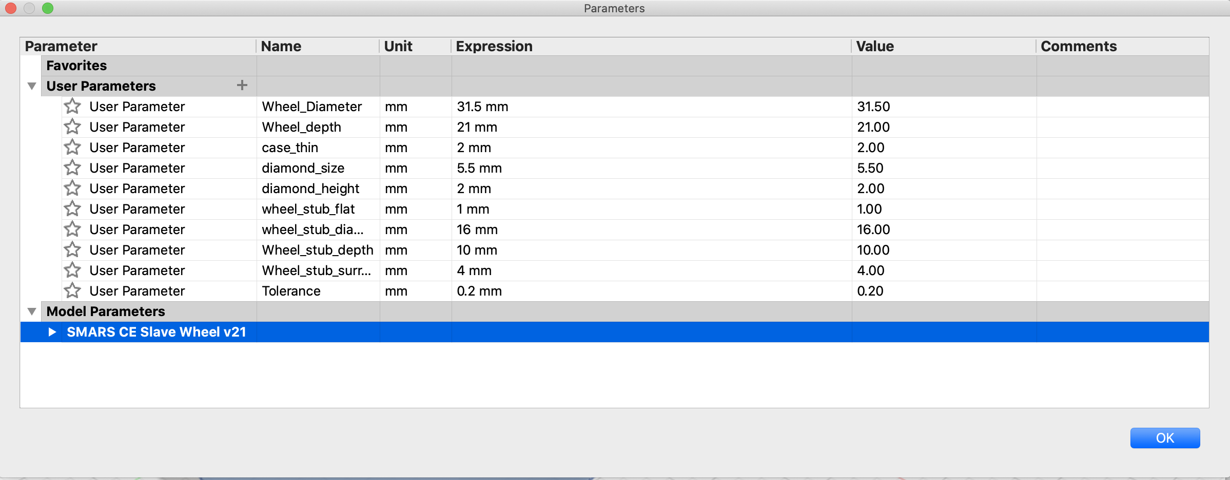
Dimensions Table
The table below shows the key parameters that drive the wheel design.
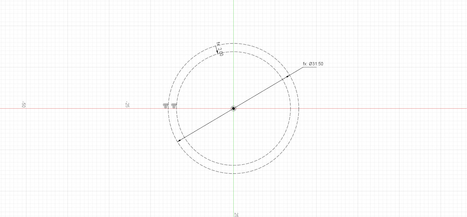
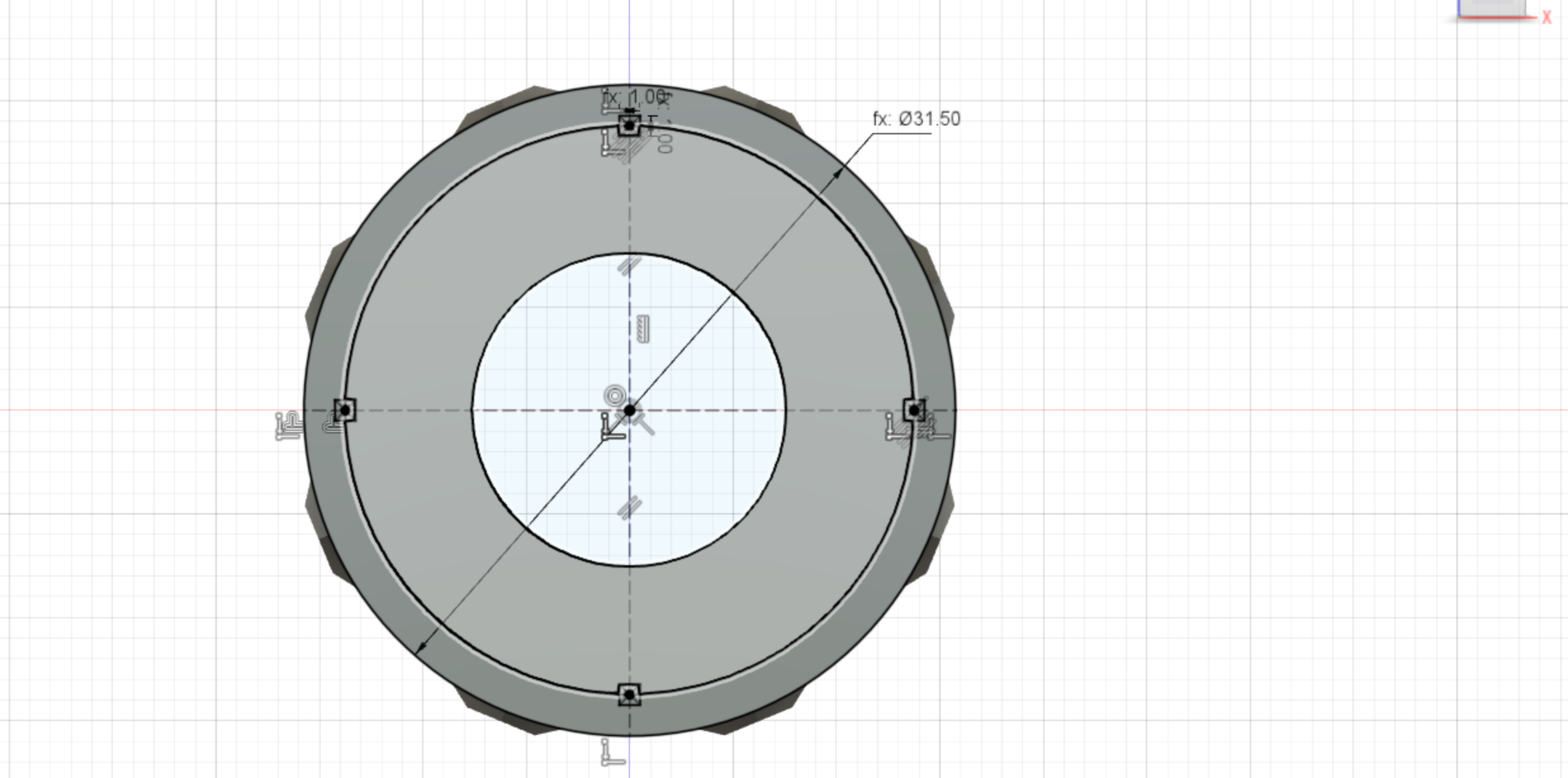
Base Sketch
The first sketch lays down the main outline of the unpowered wheel.
Dimensions:
- Wheel_diameter = 31.5mm
- offset = 2mm
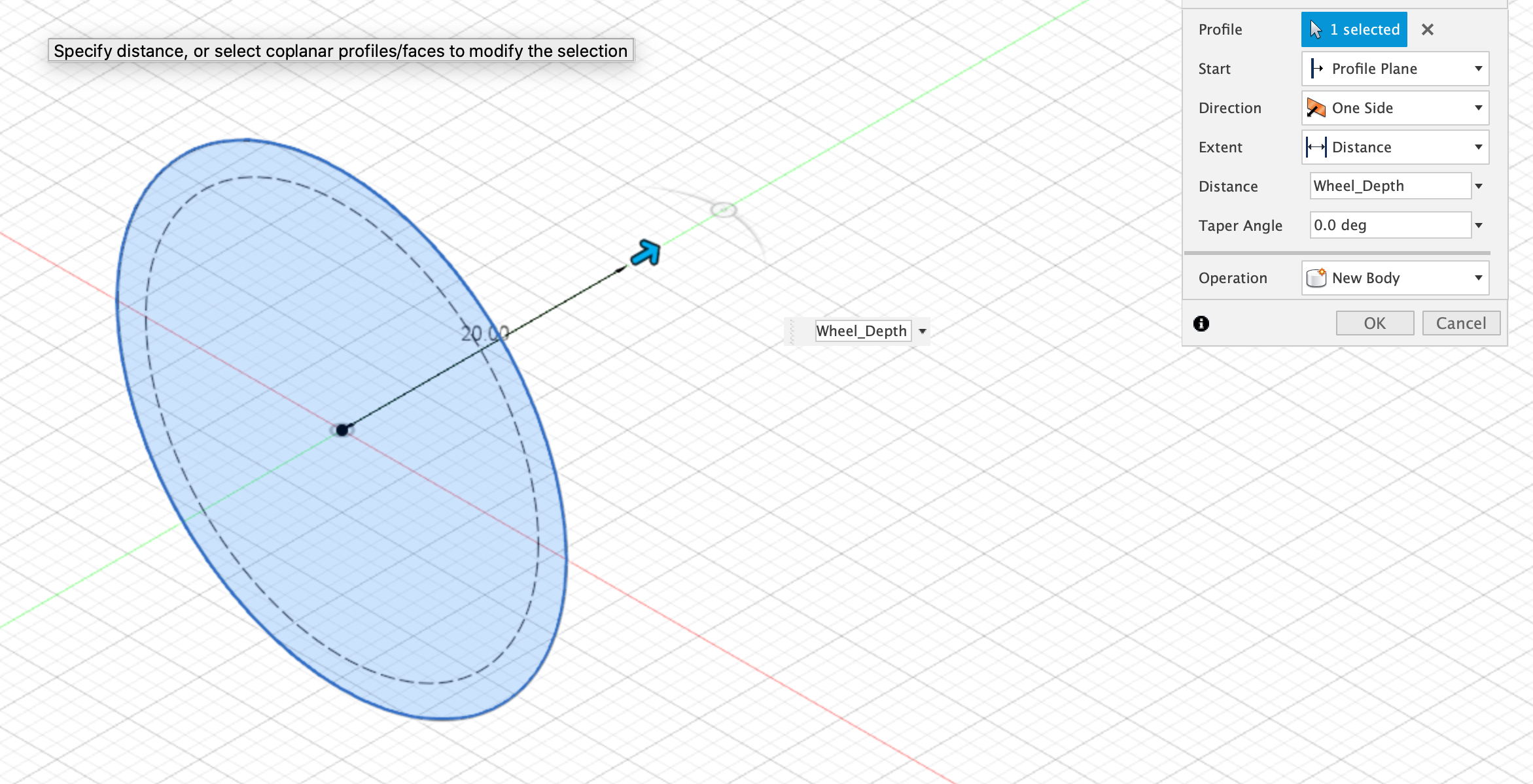
Extrude Base Sketch
Now extrude the base sketch by the Wheel_Depth:
Dimensions:
- Wheel_Depth = 21mm
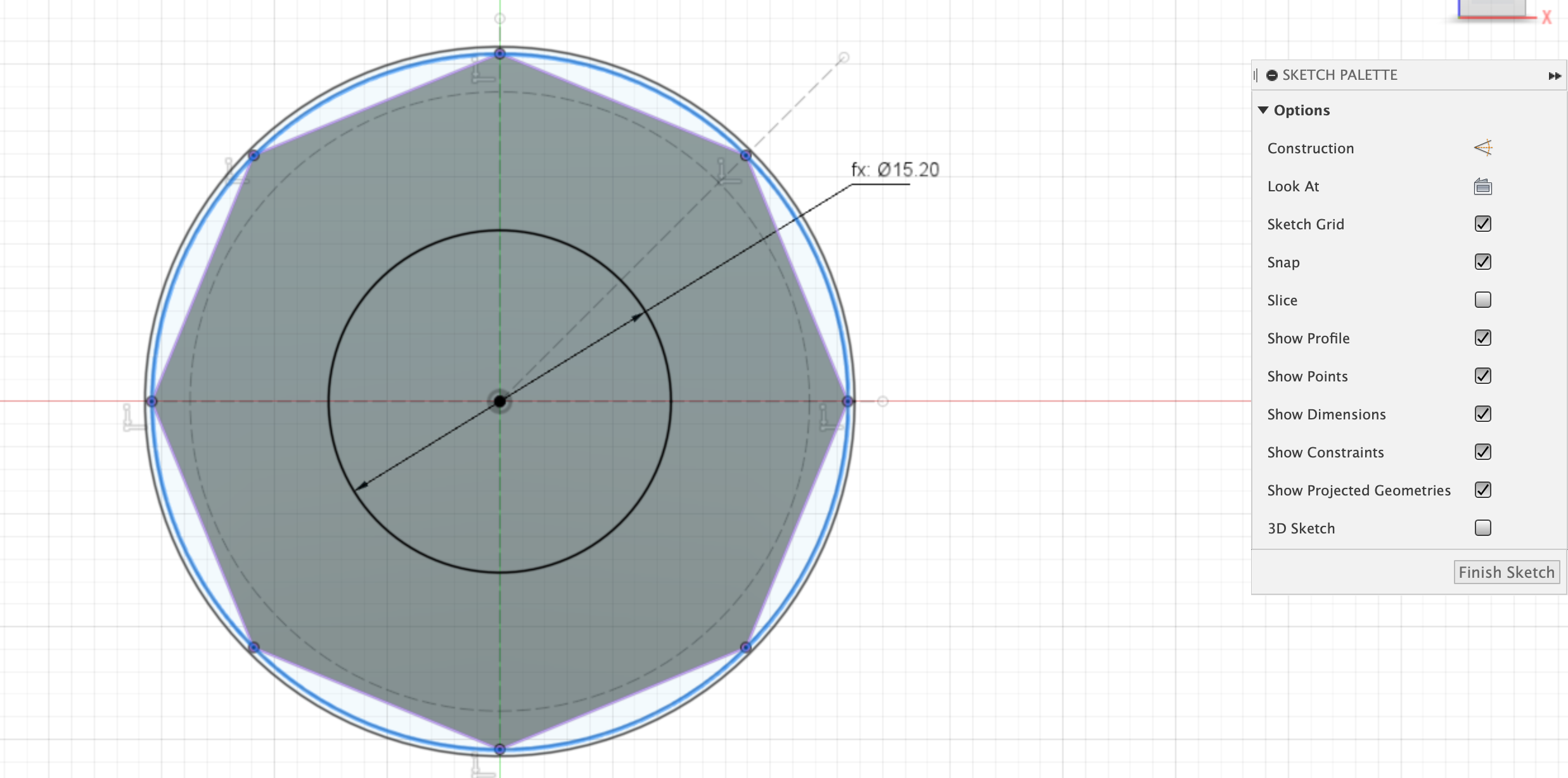
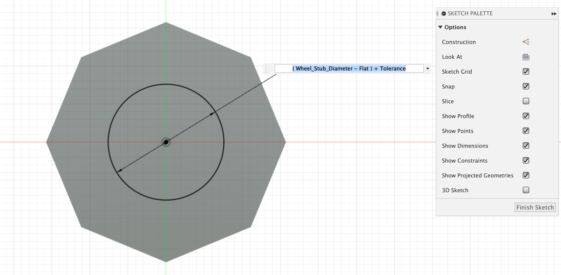
Create Octogon
Create a new sketch on the extruded body, this will be used to create the octagonal faces. Use the inscribed Polygon tool to quickly create an octogon.
Dimensions:
- Inner wheel = (Wheel_Stub_Diameter - Wheel_Stub_flat) + Tolerance (15.20mm)
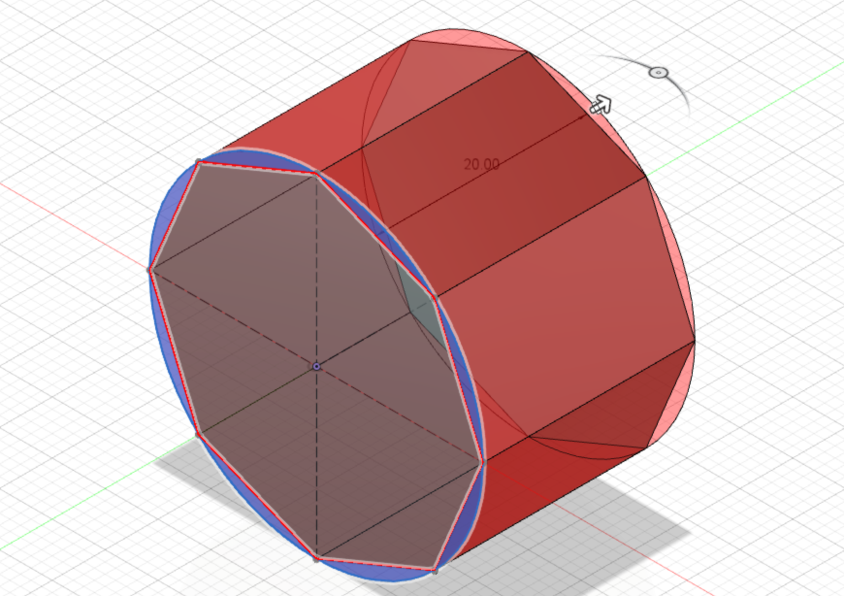
Extrude-Cut Octogon
Finish the sketch and then use the ‘push-pull’ to extrude the areas outside of the profile to form a 3d Octogon.
Create Sketch - Stub cutout
Create a circle from the origin with the formula: (Wheel_Stub_Diameter - Wheel_Stub_flat) + Tolerance. The Tolerance value is used to make the wheels fit over the chassis wheel stubs. If the fit is too tight or too loose, try adjusting this value by 0.1mm at a time.
Dimensions:
- Inner wheel = (Wheel_Stub_Diameter - Wheel_Stub_flat) + Tolerance (15.20mm)
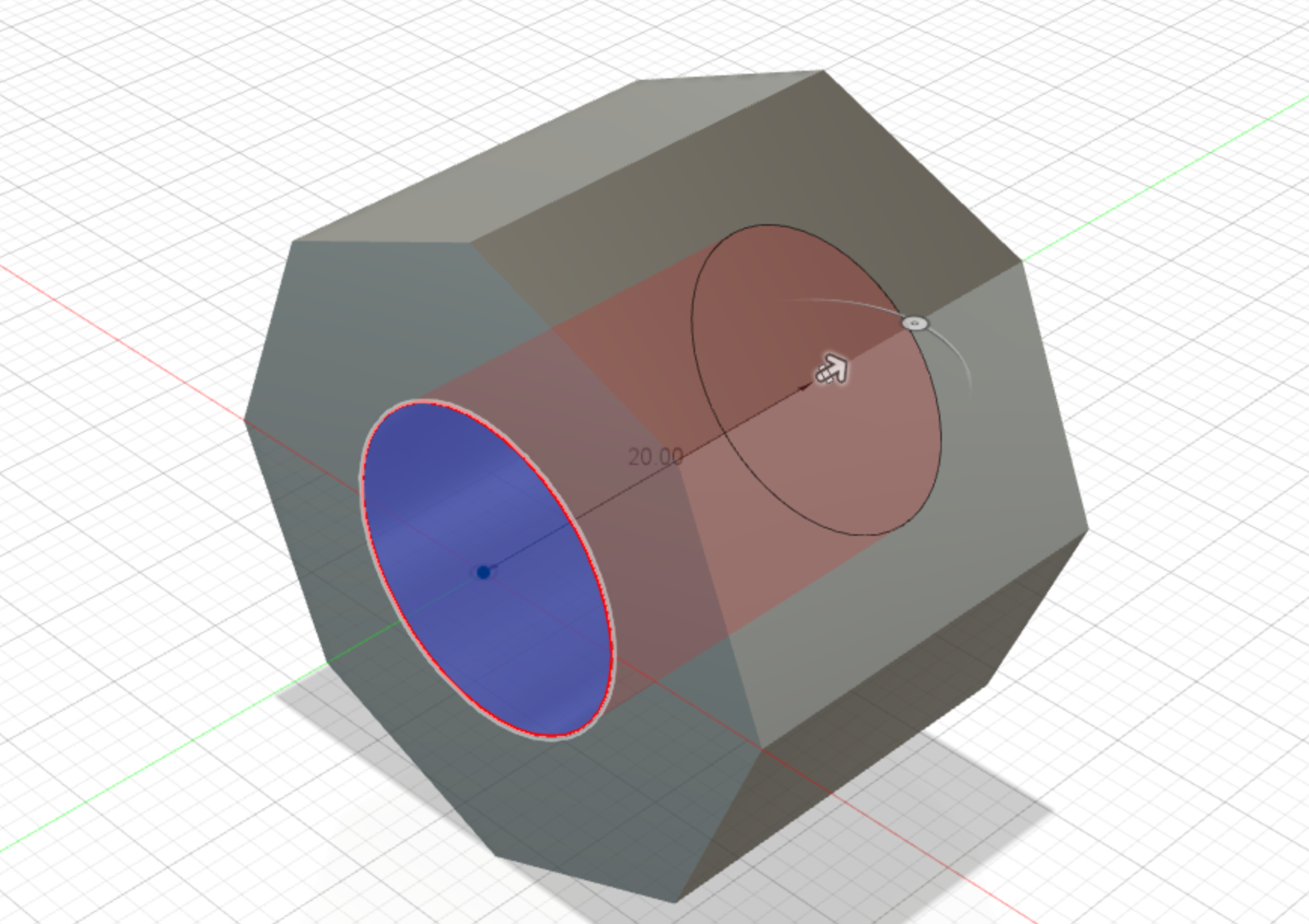
Extrude-Cut the Stub Wheel
Finish the sketch and then use the ‘push-pull’ to extrude-cut the wheel body.
Dimensions:
- cut all the way through the body
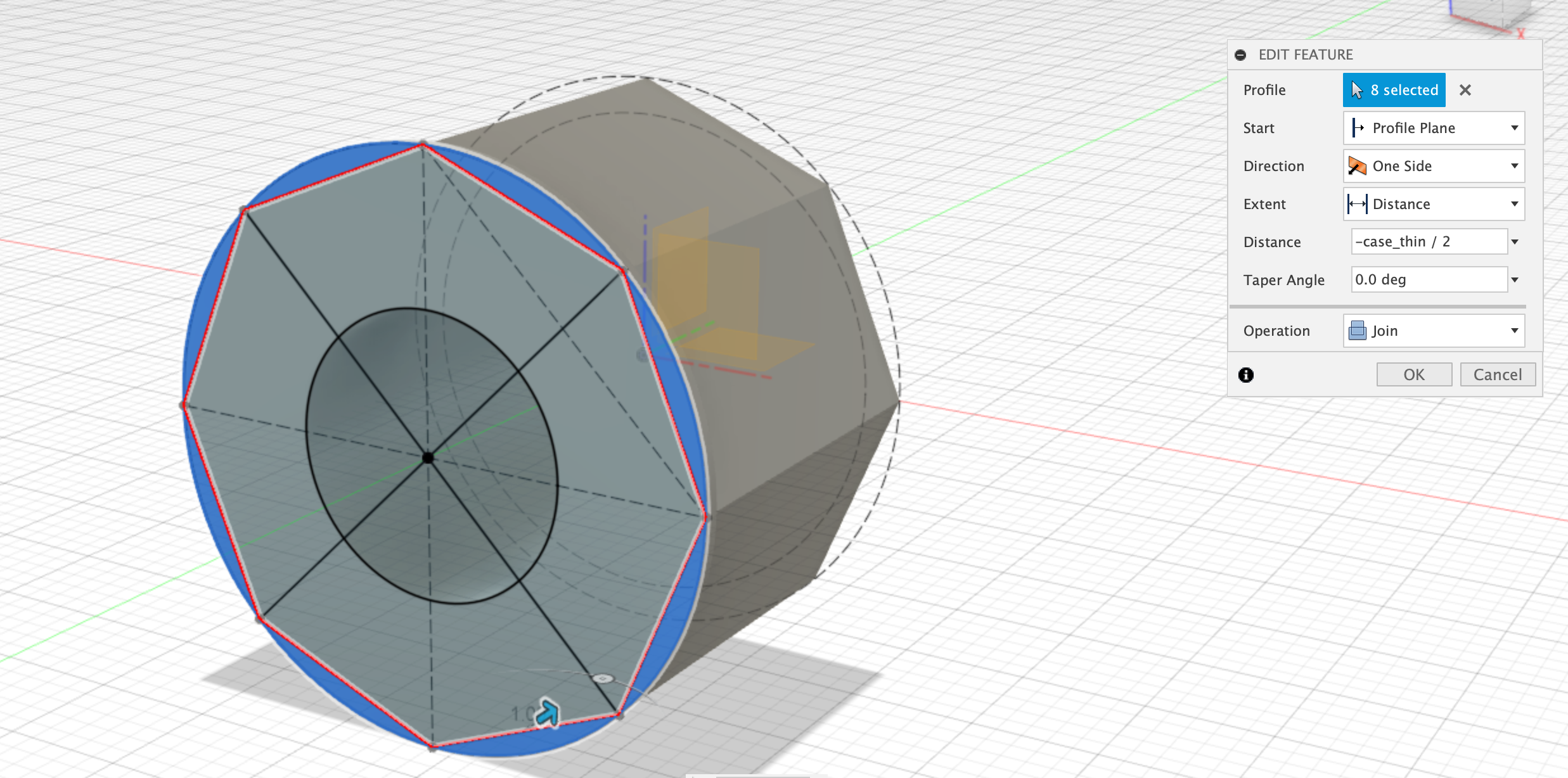
Extrude Join Rim
Make sure the sketches are visible and then use the side profile to extrude-join a 1mm rim.
Dimensions:
- Rim = 1mm
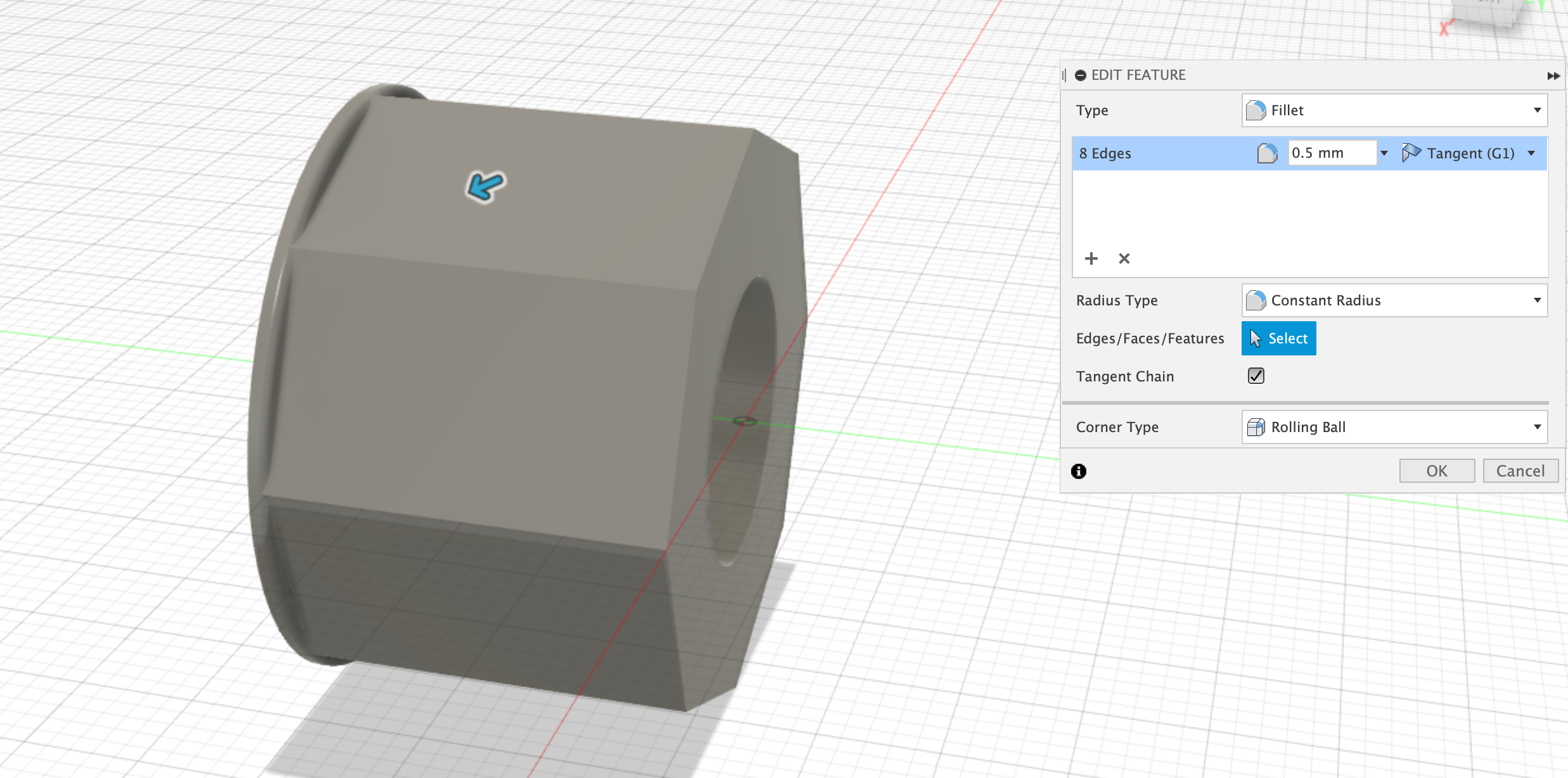
Fillet Rim
Select the newly created rim, and then apply a 0.5mm fillet to the inside edge.
Dimensions:
- Fillet = 0.5mm
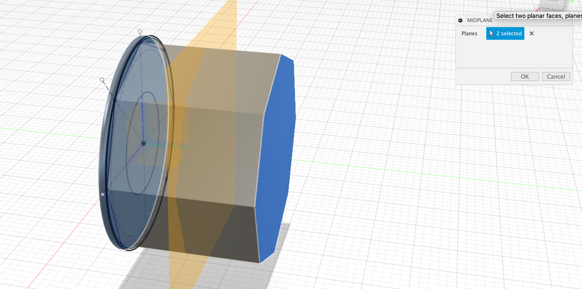
Create Midplane
Select the front and back faces of the wheel and then use the construction menu to select Create Midplane. This will create a new construction plane right down the middle of the wheel. We can use this in the next step to mirror the rim.
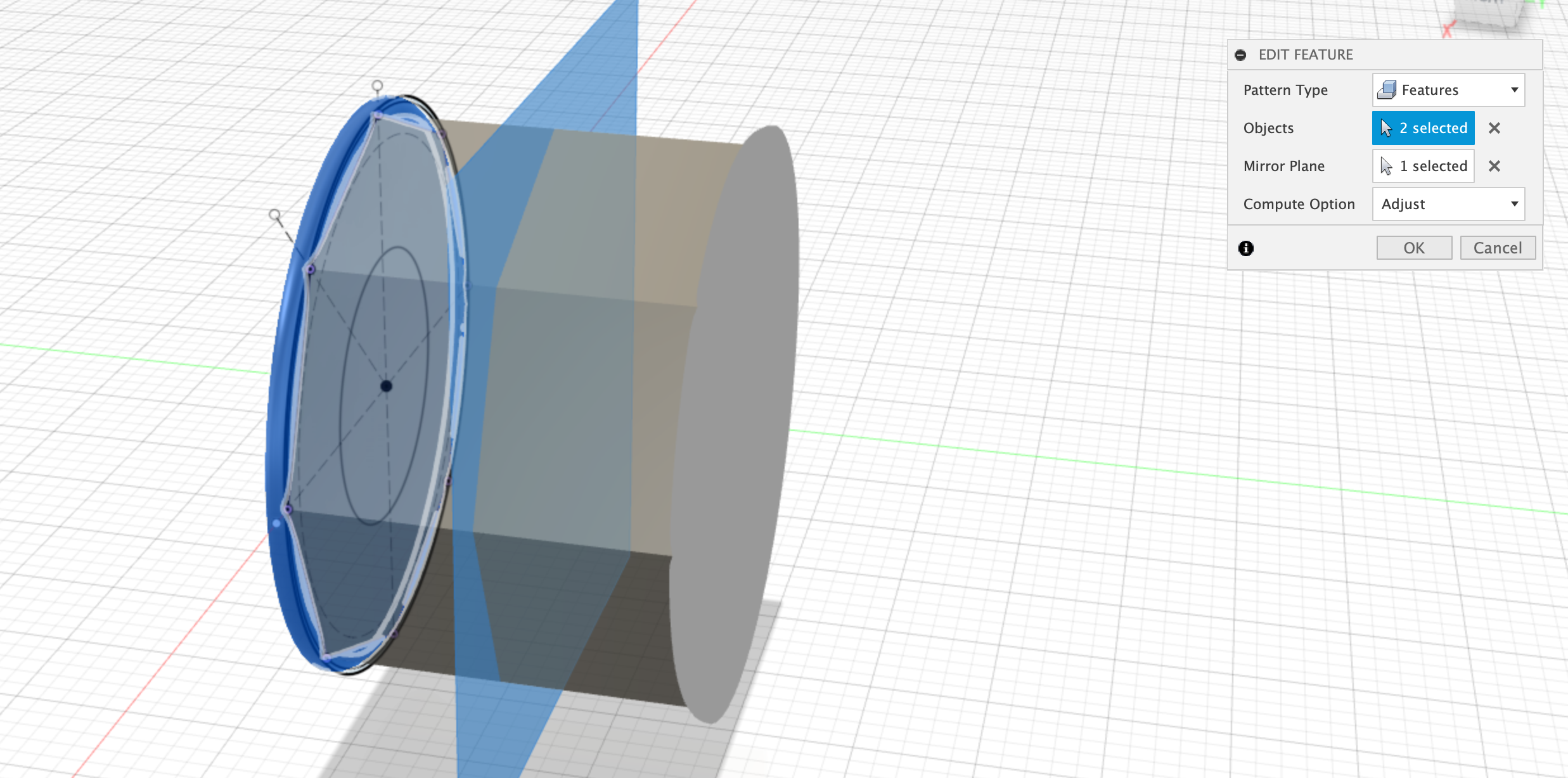
Mirror Rim and Fillet features
Create a mirror pattern and select the two features prior to the midplane - the Rim Extrusion and the Rim Fillet, Select the newly created midplane as the mirror plane.
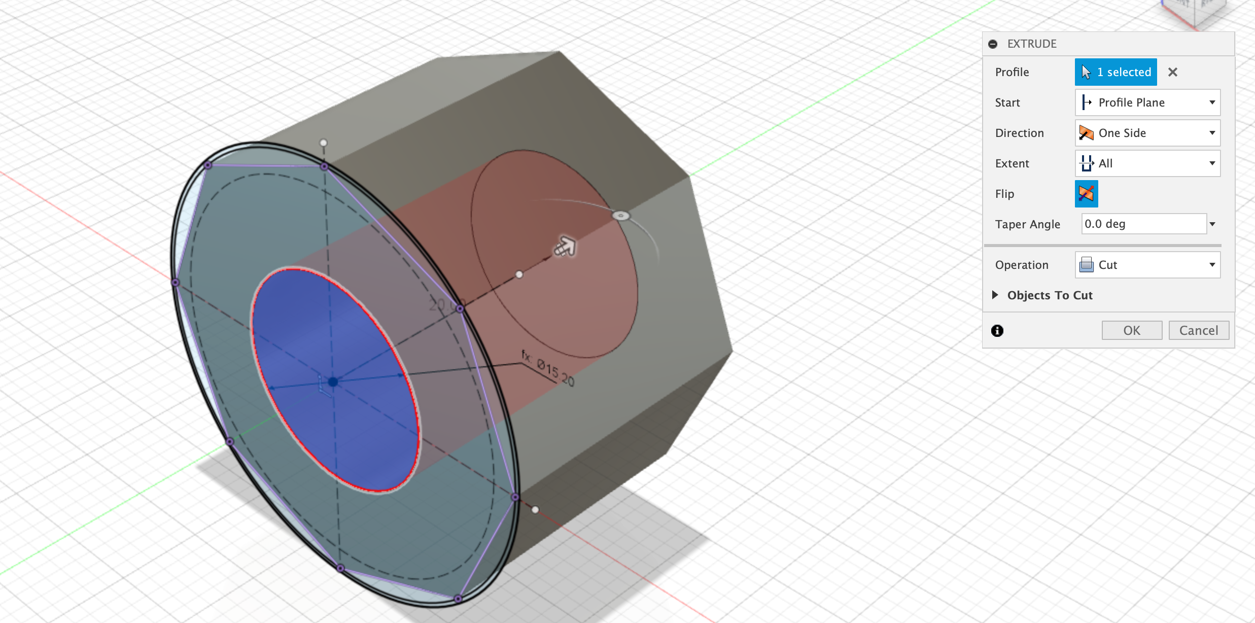
Extrude-Cut the center
You may need to extrude-cut the center again if the Rim feature filled the center hole back in.
Dimensions:
- Extrude-cut all the way through
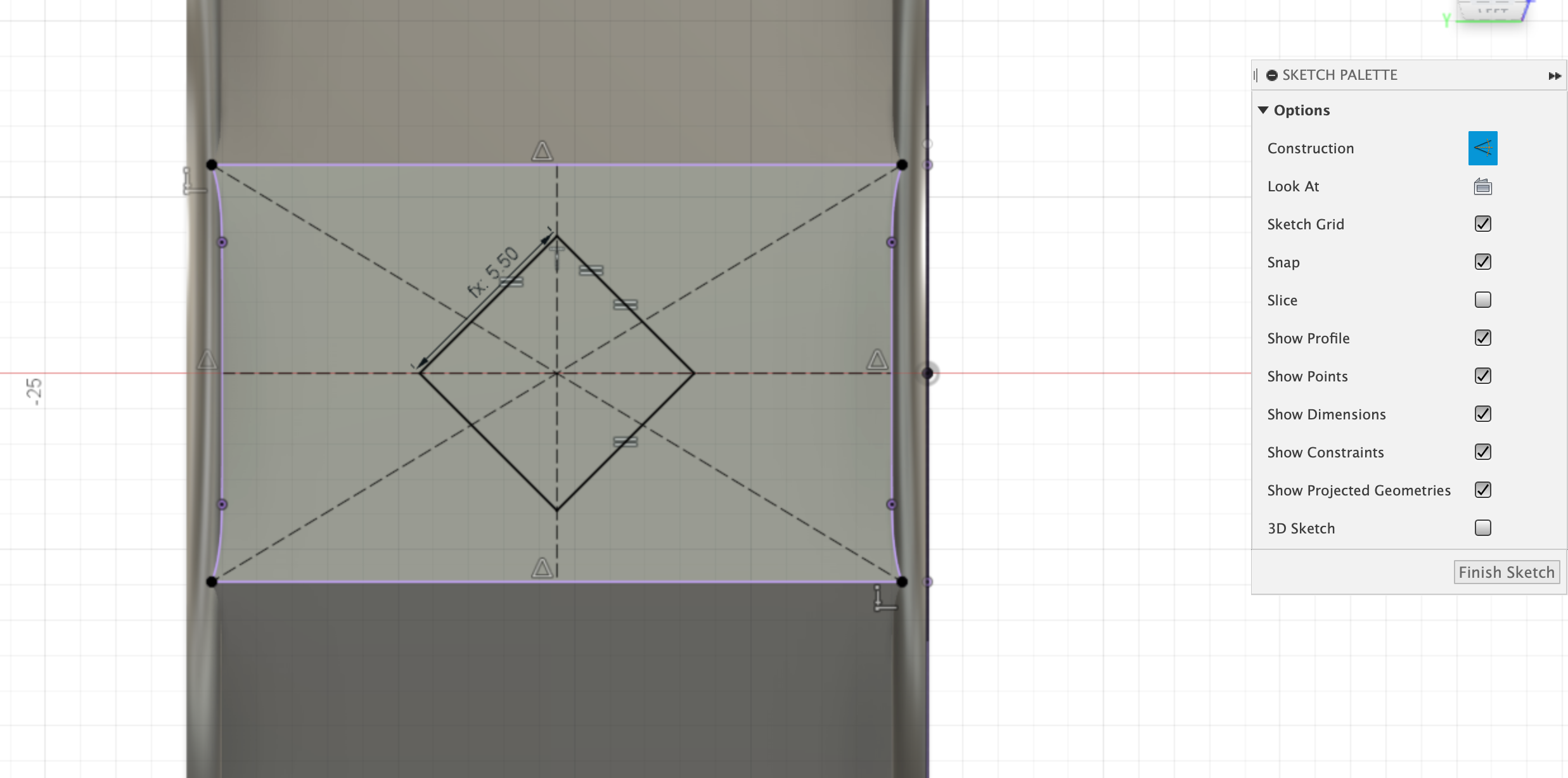
Create the Diamond sketch
Next select one of the top faces of the octogon and create a new sketch. Layout a couple of construction lines to place a diamond in the middle of the sketch.
Dimensions:
- Diamond_size = 5.5mm
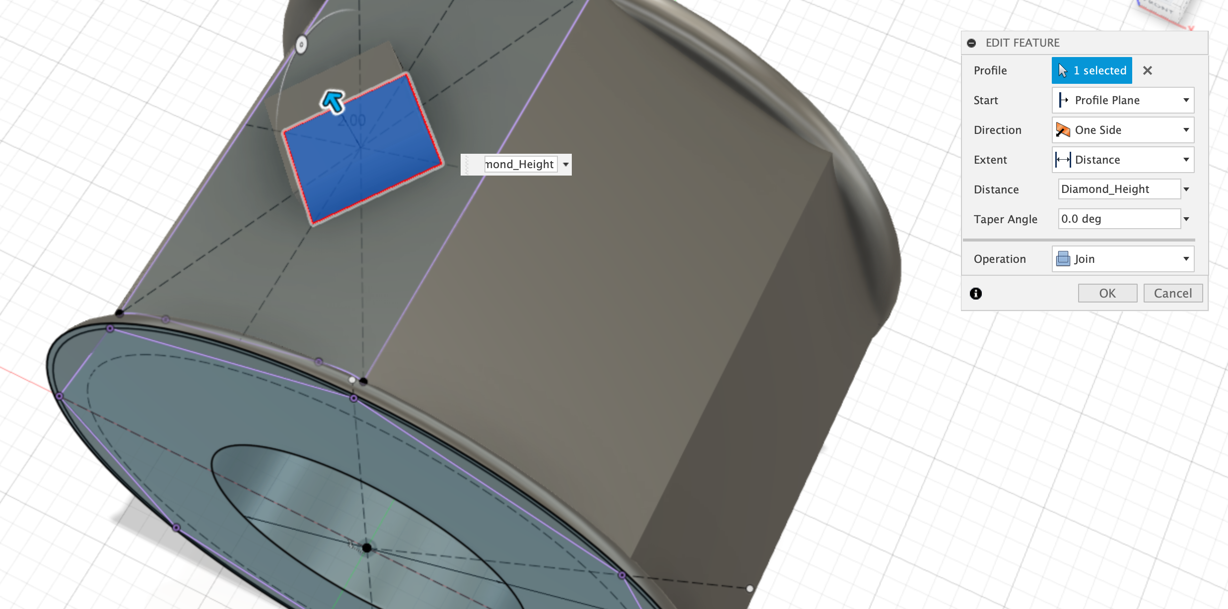
Extrude Diamond
Use the ‘push-pull’ command to extrude the diamond up by the Diamond_height.
Dimensions:
- Diamond_height = 2mm
Chamfer Diamond
Use chamfer command to apply a 1.5mm chamfer to the four edges of the diamond.
Dimensions:
- Chamfer = 1.5mm

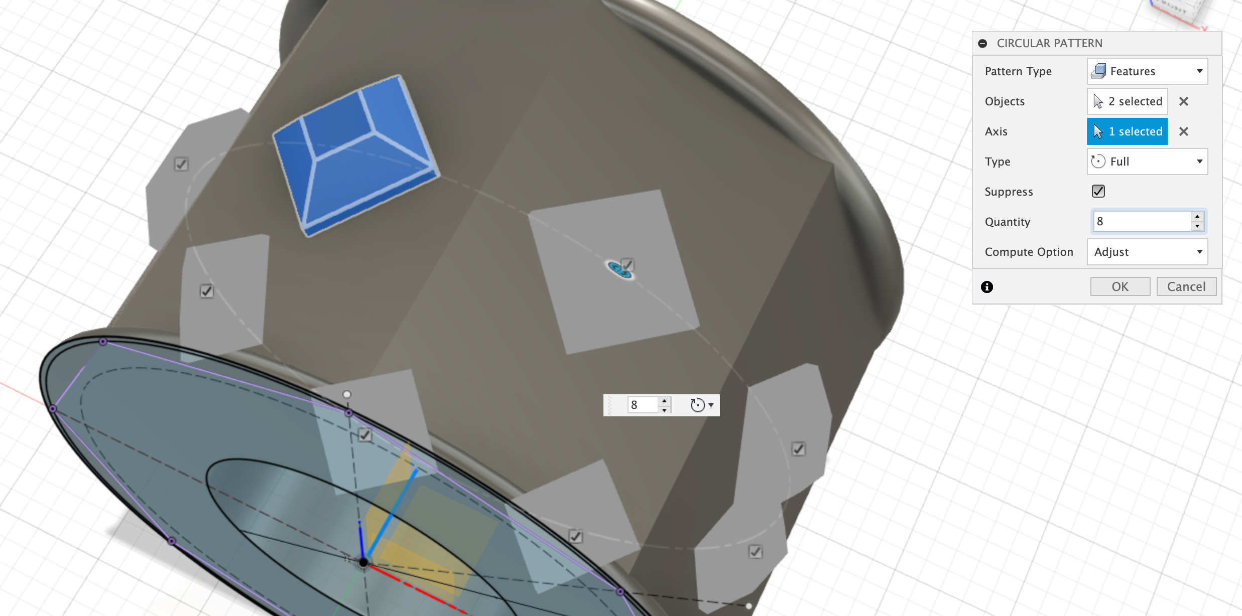
Circular Pattern the Diamond
Use the Circular pattern tool to create 8 copies of the two features you have just created - the extrude diamond and chamfer diamond features. Use the origin as the center of the circular pattern.
Dimensions:
- Circular Pattern = x8
Create Inner sketch
Create a new sketch on the side of the wheel. Project in the outside edge, the offset and the center to help provide references to this sketch, from the base sketch. Create 4 squares with the origin of the square being tangent to the offset circle.
Dimensions:
- 4x Squares = 1mm each side.
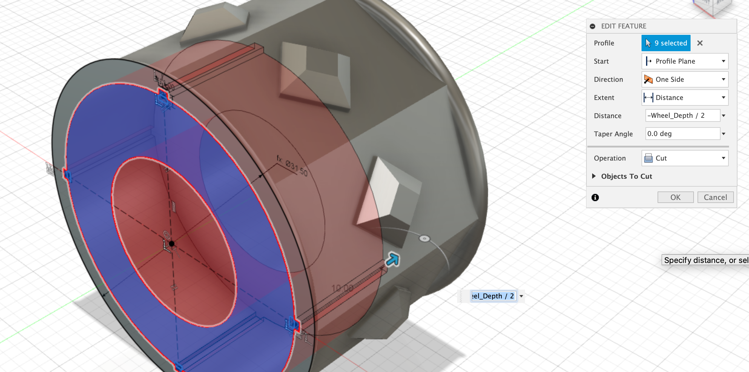
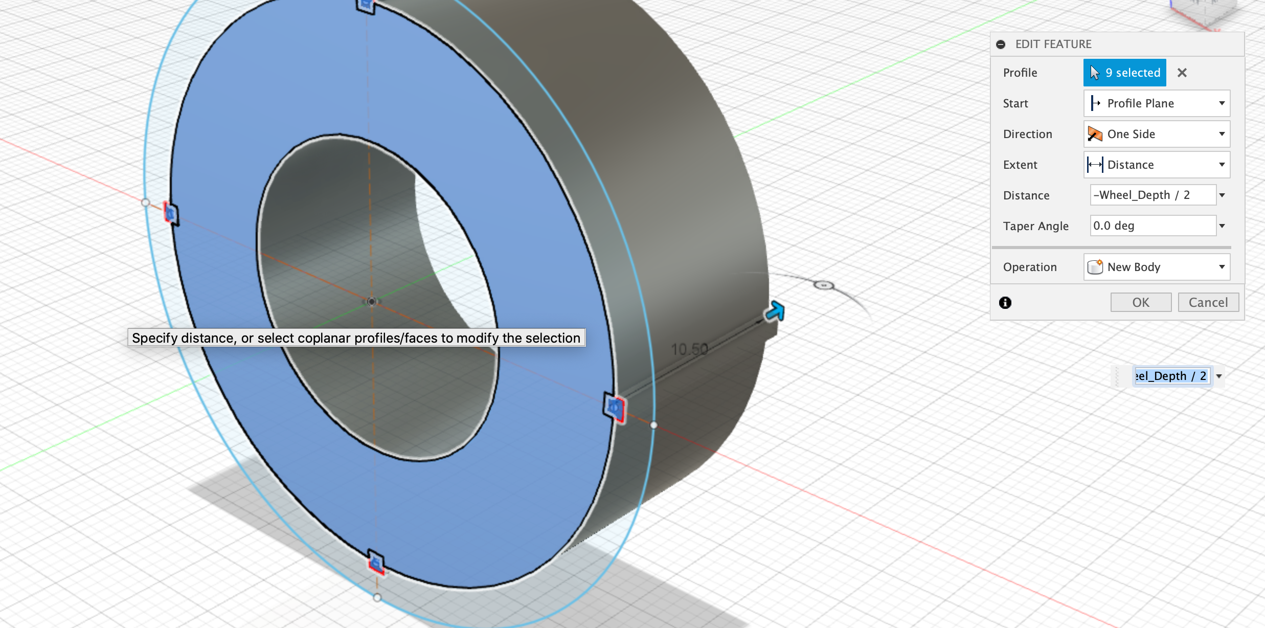
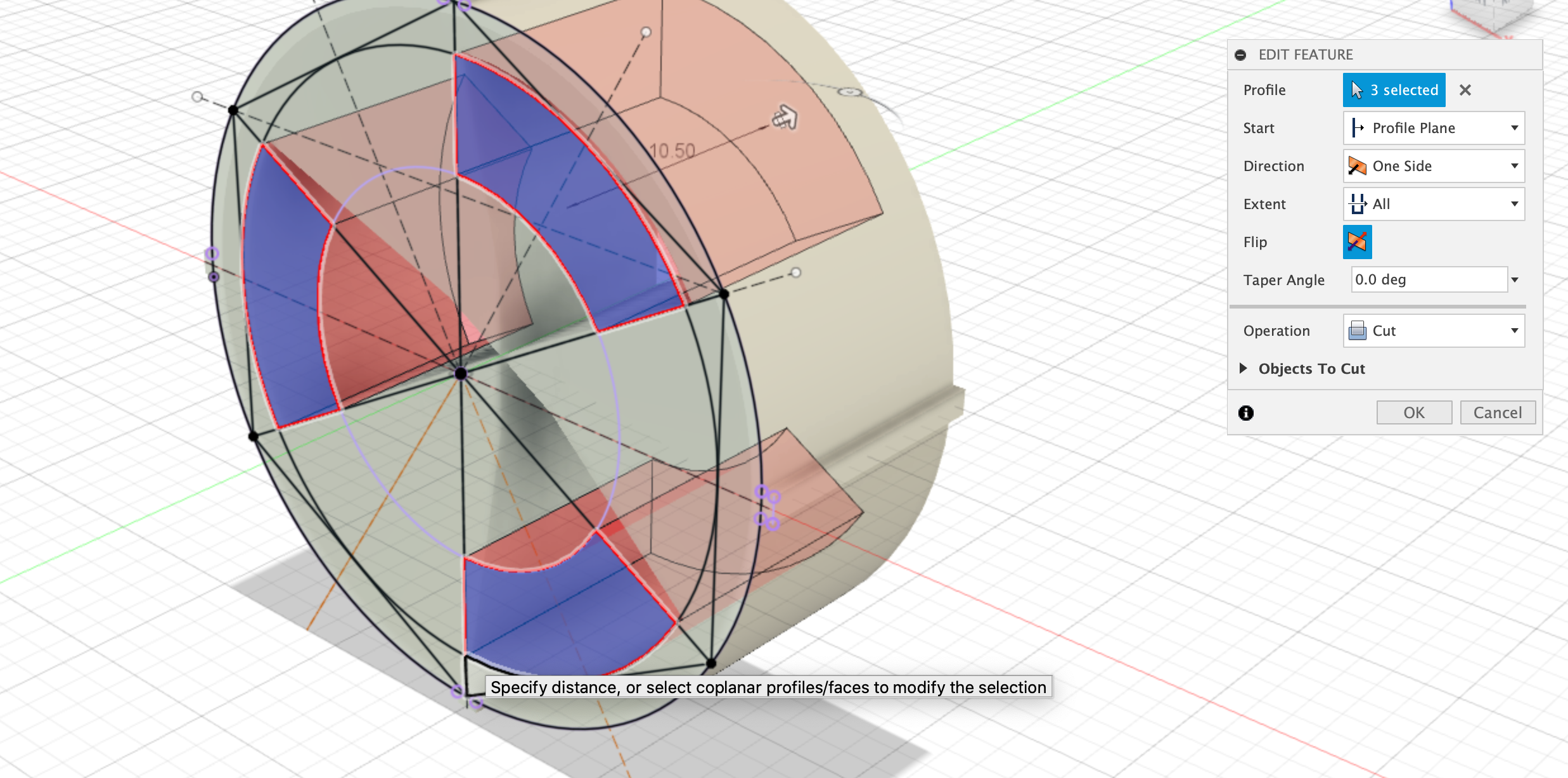
Extrude-cut Inner
After finishing the sketch, use the ‘push-pull’ commend to extrude-cut the newly created inner wheel profile. Extrude the cut by half the wheel_depth.
Dimensions: Extrude-cut Depth = Wheel_depth / 2 (10.5mm)
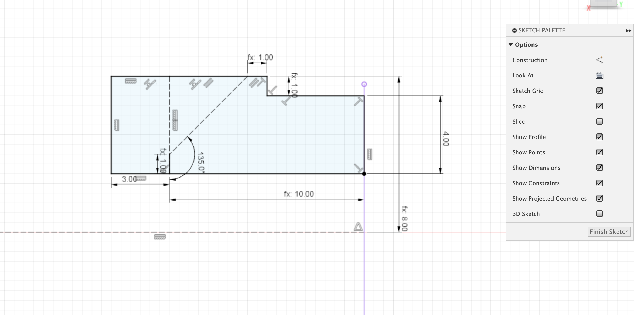
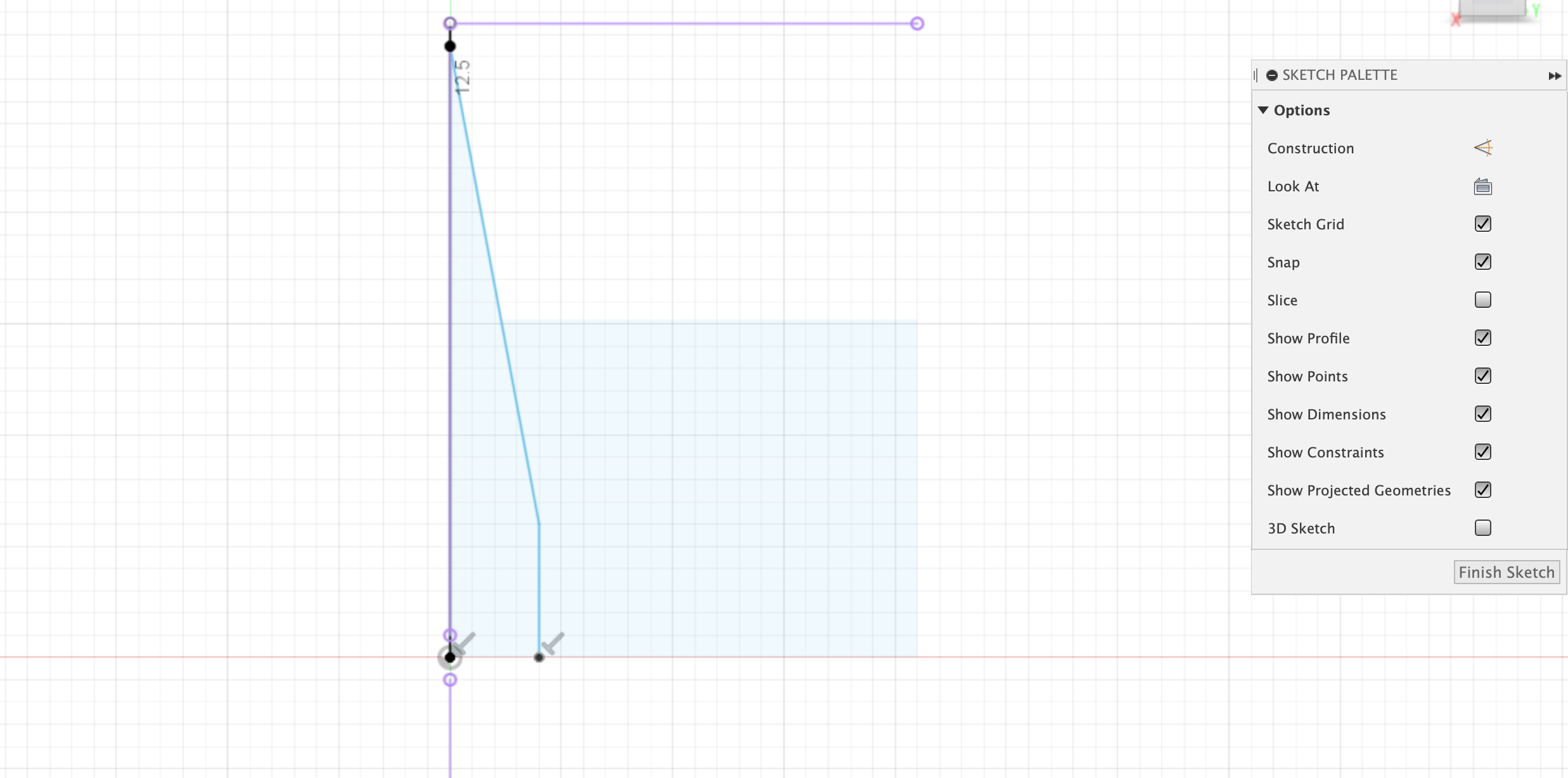
Create Stub Profile
Use the origin to create a new sketch on a plane that runs through the center of the wheel. This profile will be used to revolve-cut the wheel stub out of the back of the wheel body. This makes the mechanical joint between the SMARS chassis and the unpowered wheel.
Use the reference diagram below to dimension the sketch.
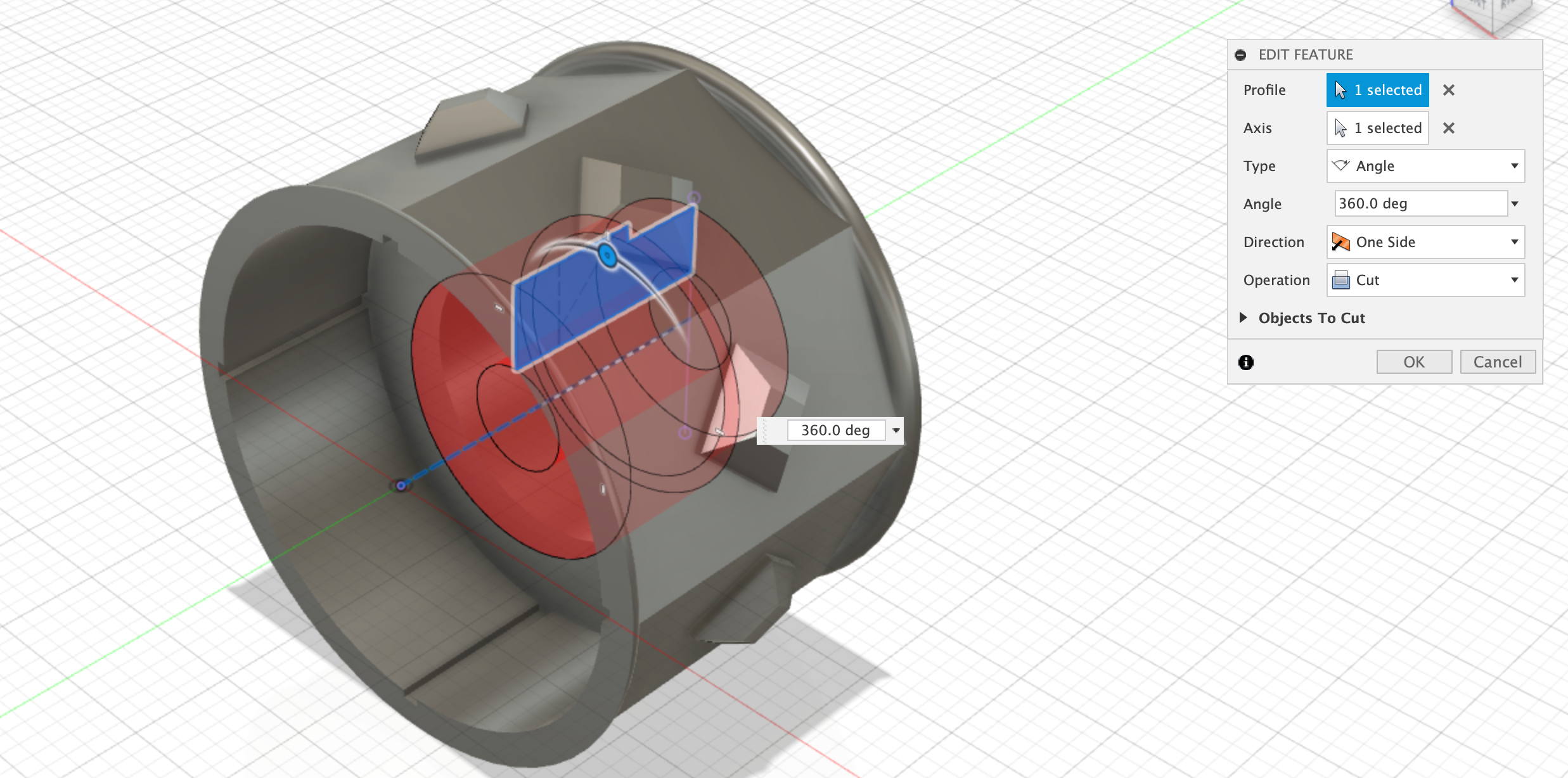
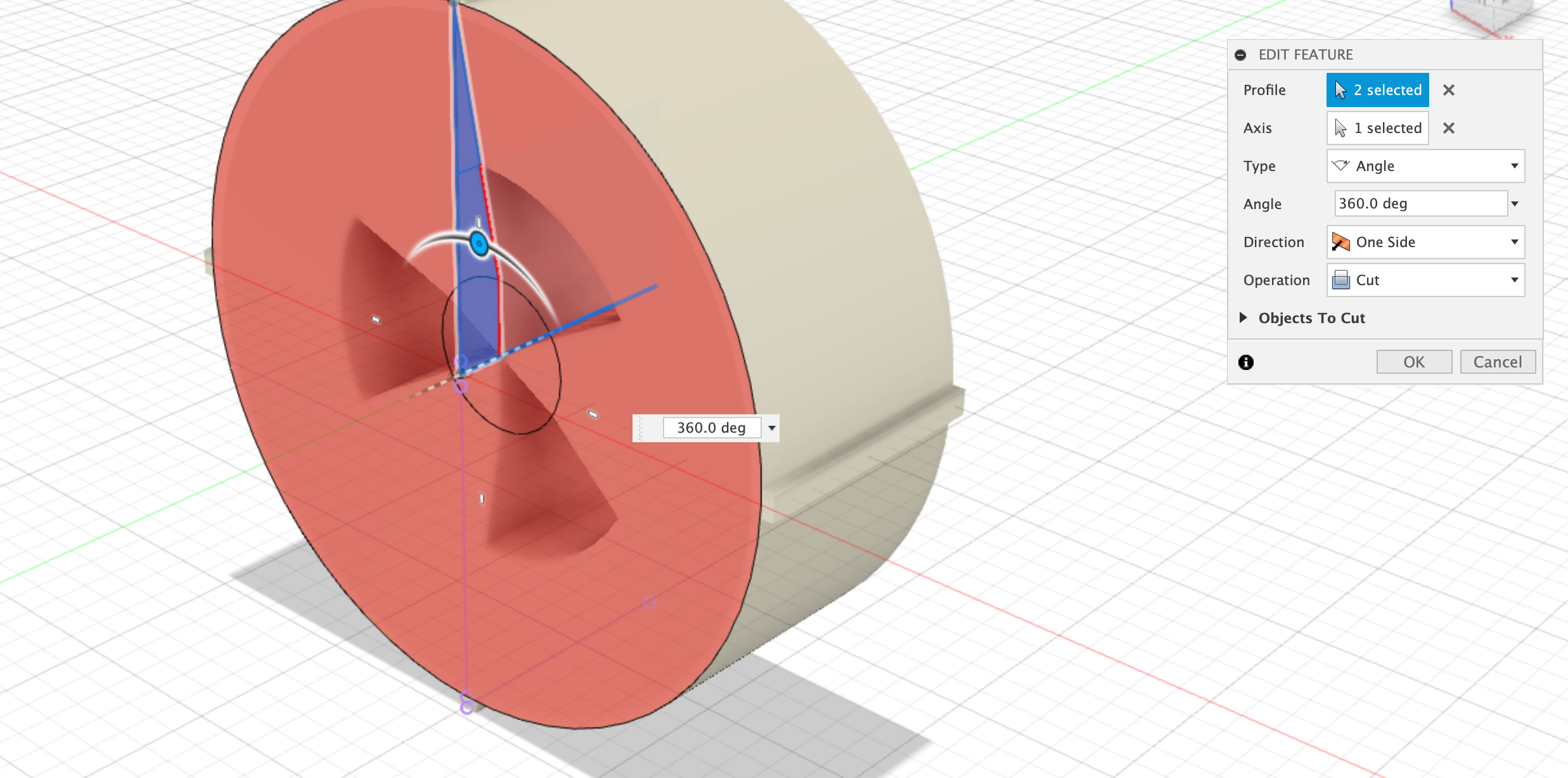
Revolve-Cut Stub
Use the revolve command to apple a cut to main body. This profile will create the mechanical join between the wheel and chassis-wheel stub.
Dimensions:
- Revolve-Cut - all the way through.
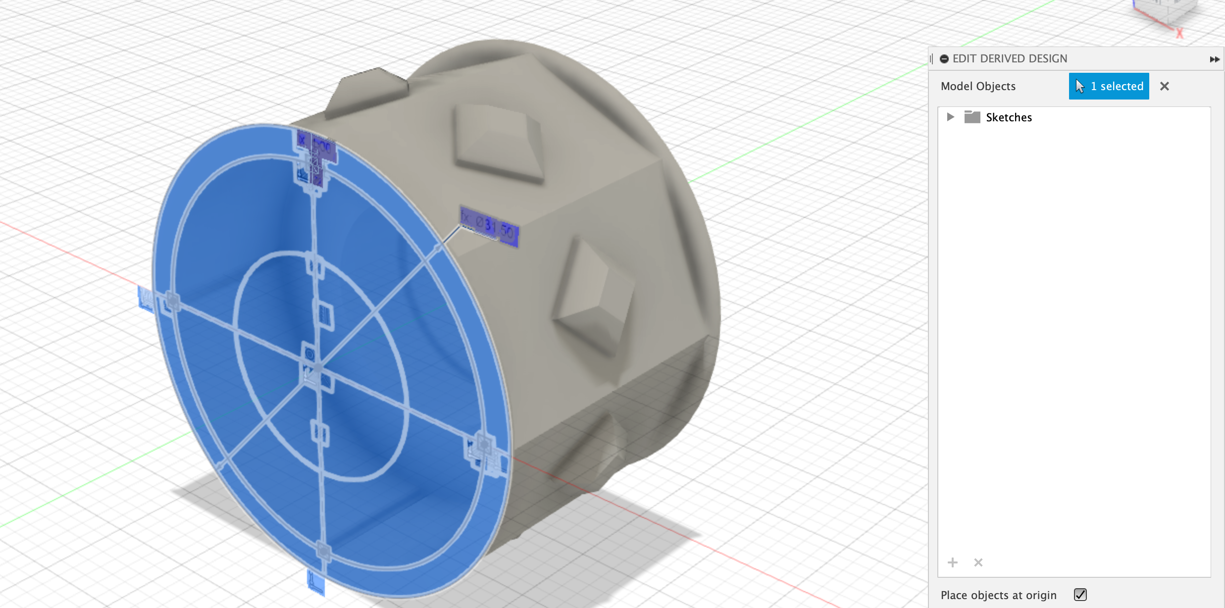
Derive Powered Wheel
Save the unpowered wheel design and create a new Design - save this new design as ‘Powered Wheel’. Use the Insert and Insert Derive command to open the unpowered Wheel design, and then just select the Body to bring this into the Master wheel design.
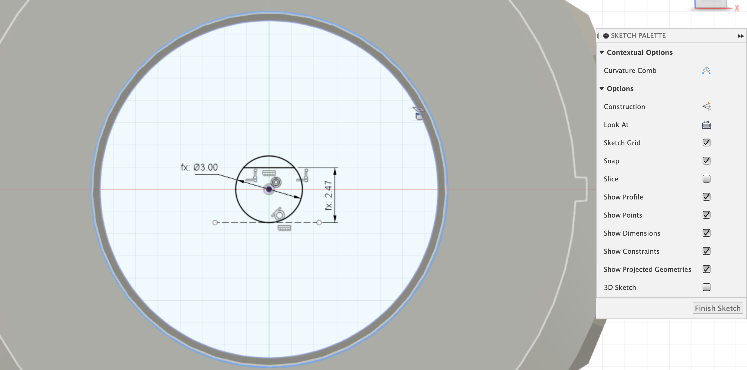
Create Powered Wheel Sketch
Select the back of the wheel body and create a new sketch. Create a circle at the origin, and two horizontal lines. The circle represents the motor spindle. The bottom line should have a tangental constraint to the bottom of of the circle, the top line should be 2.47mm away from the bottom line.
Dimensions:
- Spindle = (3mm + tolerance)
- Spingle_flat = 2.47mm
Extrude-Join master wheel
Using the sketch just created, extrude-join it to the front inner surface of the wheel.
Dimensions:
- Extrude-Join depth = to object - inner surface
Inner Wheel
Save the Powered Design and create a new design and save it as ‘Inner Wheel’. Use the Insert -> Insert Derive command to open the unpowered Wheel design and select the inner wheel sketch profile.
With the inner sketch selected, use the ‘push-pull’ command to extrude the wheel inner by half of the wheel_depth (10.5mm).
Dimensions:
Inner Wheel extrude = Wheel_Depth / 2 (10.5mm)
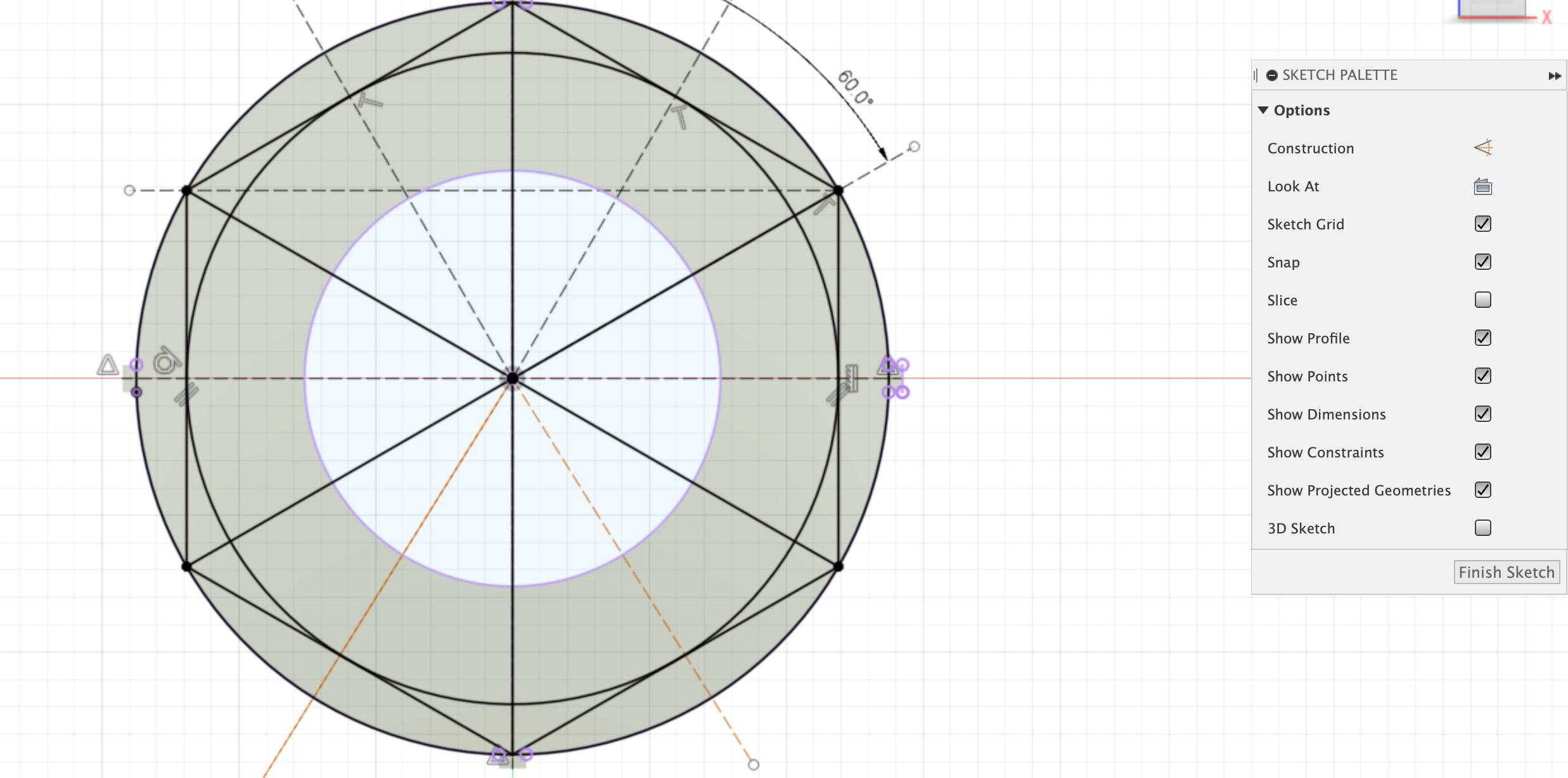
Create the inner wheel design - 3 spoke design
We will now use the Polygon -> Inscribed Polygon command to create a circle that is the offset by 1mm from the outside edge of the inner wheel, with 6 sides.
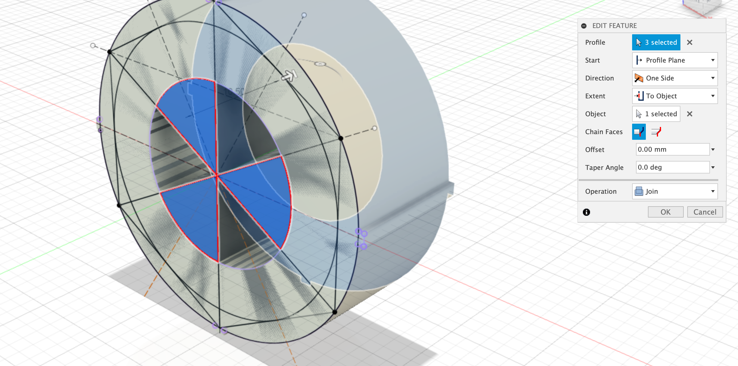
Extrude polygon
Select 3 of the polygons to extrude-join to the inner wheel body. Extrude all the way through the body.
Dimensions:
- Extrude - all the way through
Create tool profile
Now create a sketch on the inside flat surface of one of the spokes, and create the profile as shown below. The dimensions of the profile are up to you to decide, on how you want the wheel to look.
Revolve-cut the tool profile
Select the profile created above, and use the revolve command to create and cut the spokes.
Extrude-Cut Inner spokes
Use the ‘push-pull’ command to extrude-cut the upper part of the spokes. This should complete the design of the inner wheel.
You should now have 3 designs:
- Unpowered Wheel
- Powered Wheel
- Inner Wheel
You can use the inner wheel sketch derived from the unpowered wheel to create all kinds of new designs and variations. Each of these will be able to slot into the inner part of the wheel. You can use different colours of filament to make the designs more interesting.